
Water Quality Monitoring System Using GSM Module
Abstract
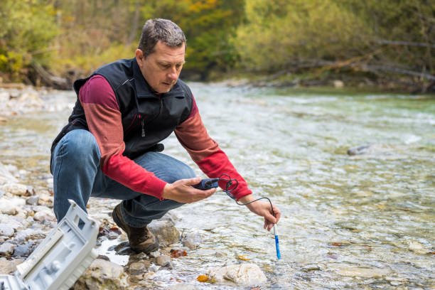
The Arduino based water quality monitoring system using GSM module project, All living things require water to survive, and it is not possible to live without it. One of the worst types of this environmental pollutant is water pollution. Whether it’s the water supply in our homes or the juices that are made by businesses and that we consume, the quality of the water that we consume has a significant impact on how long we live. Biological, chemical, radiological, and other aspects of the water are referred to as its quality. One of the main concerns for the developing economic system is water pollution. Due to rapid urbanization and industrialization, water quality is declining year over year, which results in water-borne illnesses and has a negative impact on turquoise culture. It is important to check the quality of the water because 65 percent of the country’s drinking water originates from underground sources. The envisioned system demonstrates a design and development of a low-cost system for real-time monitoring of water quality using Arduino.
Introduction
All living things require water as a necessity, and it is impossible to survive without it. Environmental pollution has grown to be a big issue as a result of industrialization and technological growth. One of the worst forms of environmental contamination is water pollution. Water quality is crucial to our survival. Any imbalance in water quality would have a negative impact on human health as well as the environment. In this project, The crucial water parameters are measured in this water quality monitoring system using a sensor. According to past studies, the most important water parameter that typical users need to keep an eye on is our water pH level, this system will send an alert message with the help of the GSM module and a buzzer will be activated
Components Required
Hardware Requirements
- Arduino Uno : Arduino Uno is a microcontroller from the Arduino Family. It was developed by Arduino. cc and is based on the Microchip ATmega328P microcontroller. Uno has 20 I/O pins, 6 are analog pins and 14 are digital pins.
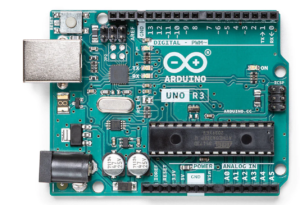
For more details, pinout and datasheet, you can visit : https://docs.arduino.cc/hardware/uno-rev3
- Ph sensor sen0161:ph sensor used to know the acidity and alkalinity of the water between the range of 0-14. Every ph sensor works differently to measure the quality of the water.
- turbidity sensor: turbidity sensor is used to measure the cloudiness or haziness of the water
- GSM: GSM stands for Global System for Mobile Communication. which can be monitored through SMS service.
- Buzzer: An Audio Signalling Device. Buzzers can be mechanical, electromechanical, or piezoelectric. It produces an alarming sound when triggered. Used in various applications like Game buzzers, Alarm Buzzers, Trains, etc.
Software Requirements
- Arduino Ide : Arduino IDE (Integrated development environment) is software that is used to dump the program into boards. Arduino- IDE’s major use is to build electronics-related projects. Arduino is an open-source platform simple and easy-to-understand platform for coding.
HOW TO INSTALL ARDUINO IDE CLICK ON THE LINK :
https://techieyantechnologies.com/2022/10/installation-of-arduino-ide/
Block diagram
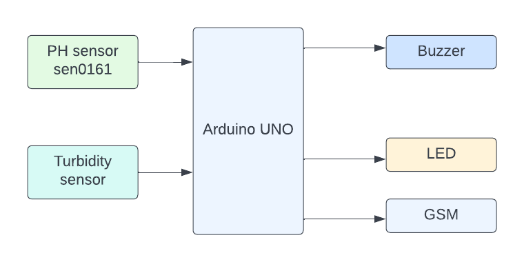
The block diagram of water quality monitoring system describes the relationship between the input devices and output devices. Here, in this case, the input device is a ph sensor and turbidity sensor that sends the information to Arduino where the output is transmitted to specific devices such as GSM, and buzzer and led these devices to receive the information from the Arduino which is given by input devices.
Flow Chart
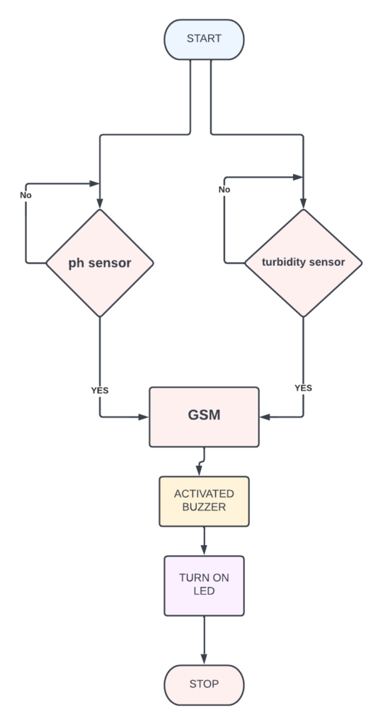
A flowchart is a diagram that shows a process’ individual steps in their proper order, similarly, the following flowchart tells about the steps involved in the project and the sequential flow of the code also. So as it starts, first, it reads the sensor’s value if the sensor’s value is greater than the given condition then turns on the buzzer, else it will be turned off. readings will be monitored via SMS by using the GSM module.
*website used to make Flow Chart and Block Diagram : https://www.lucidchart.com/pages/
Pin Wiring
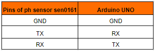
Ph sensor sen0161
The ph sensor has 3 pins GND, TX, and RX where GND is connected to the GND of the Arduino Uno. TX is connected to the RX of the Arduino Uno. RX is connected to the TX of the Arduino Uno.
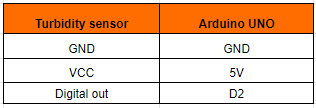
Turbidity sensor:
The turbidity sensor has 3 pins GND, VCC, and digital pin, here GND is connected to the GND of Arduino UNO. VCC is connected to 5V of the Arduino Uno. The digital pin is connected to the D2 of the Arduino Uno.
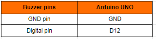
Buzzer
The Buzzer has two pins Ground and Digital pin. The GND pin is connected to the GND pin of the Arduino Uno. The Digital pin is connected to the D12 pin of the Arduino Uno.
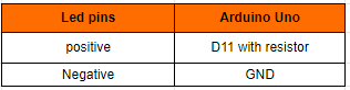
LED
The LED has two pins, (positive)+v and Ground. We connect (positive)+v to pin 11 of Arduino Uno and Ground to GND(you can connect to any ground of Uno). Making pin 11 HIGH or LOW we can activate or deactivate the led.
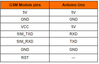
GSM Module
GSM module has 7 pins. 5v is connected to the 5v pin of the Arduino Uno. GND is connected to the GND of the Arduino Uno. VCC is connected to the 5v pin of the Arduino Uno. SIM_TXD is connected to the RXD pin of the Arduino Uno. SIM_RXD is connected to the TXD pin of the Arduino Uno. GND is connected to the GND of the Arduino Uno.
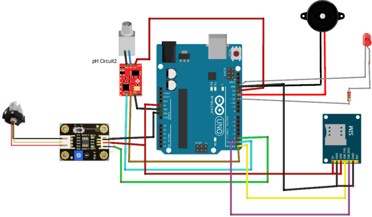
Circuit diagram
Note: make sure to take proper precautions while connecting the components.
Working
The ph Sensor measures the acidity and alkalinity of the water and the turbidity sensor is used to know the hardness of the water if the values are greater than the given range then the buzzer and led will be turned on else it remains off and gives whole monitoring values through the SMS.
Conclusion
Here, we detect the purity of the water by calculating the acidity, hardness, etc. so one can be careful about the drinking water. It also alerts if the value goes above a certain limit by SMS.
Working Code
#include <Wire.h>
#include <LiquidCrystal_I2C.h>
LiquidCrystal_I2C lcd(0x27, 16, 2);
float calibration_value = 21.34;
int phval = 0;
unsigned long int avgval;
int buffer_arr[10],temp;
void setup() {

  Serial.begin(9600); //Baud rate: 9600
  lcd.init();
  lcd.begin(16, 2);
  lcd.backlight();
  lcd.setCursor(0, 0);
  lcd.print("   Welcome ");
  lcd.setCursor(0, 1);
  delay(2000);
  lcd.clear();
}
void phsensor () {
 for(int i=0;i<10;i++)
 {
 buffer_arr[i]=analogRead(A0);
 delay(30);
 }
 for(int i=0;i<9;i++)
 {
 for(int j=i+1;j<10;j++)
 {
 if(buffer_arr[i]>buffer_arr[j])
 {
 temp=buffer_arr[i];
 buffer_arr[i]=buffer_arr[j];
 buffer_arr[j]=temp;
 }
 }
 }
 avgval=0;
 for(int i=2;i<8;i++)
 avgval+=buffer_arr[i];
 float volt=(float)avgval*5.0/1024/6;
 float ph_act = -5.70 * volt + calibration_value;
 lcd.setCursor(0, 0);
 lcd.print("pH Val:");
 lcd.setCursor(8, 0);
 lcd.print(ph_act);
 delay(1000);
}

void turbiditysensor() {
  int sensorValue = analogRead(A0);   // read the input on analog pin 0:
  float voltage = sensorValue         * (5.0 / 1024.0); // Convert the analog reading (which goes from 0 - 1023) to a voltage (0 - 5V):
  Serial.println(voltage);          // print out the value you read:
  delay(500);
}
void loop(){
  }
  #include <Wire.h>
#include <LiquidCrystal_I2C.h>
LiquidCrystal_I2C lcd(0x27, 16, 2);
float calibration_value = 21.34;
int phval = 0;
unsigned long int avgval;
int buffer_arr[10],temp;
void setup() {

  Serial.begin(9600); //Baud rate: 9600
  lcd.init();
  lcd.begin(16, 2);
  lcd.backlight();
  lcd.setCursor(0, 0);
  lcd.print("   Welcome ");
  lcd.setCursor(0, 1);
  delay(2000);
  lcd.clear();
}
void phsensor () {
 for(int i=0;i<10;i++)
 {
 buffer_arr[i]=analogRead(A0);
 delay(30);
 }
 for(int i=0;i<9;i++)
 {
 for(int j=i+1;j<10;j++)
 {
 if(buffer_arr[i]>buffer_arr[j])
 {
 temp=buffer_arr[i];
 buffer_arr[i]=buffer_arr[j];
 buffer_arr[j]=temp;
 }
 }
 }
 avgval=0;
 for(int i=2;i<8;i++)
 avgval+=buffer_arr[i];
 float volt=(float)avgval*5.0/1024/6;
 float ph_act = -5.70 * volt + calibration_value;
 lcd.setCursor(0, 0);
 lcd.print("pH Val:");
 lcd.setCursor(8, 0);
 lcd.print(ph_act);
 delay(1000);
}

void turbiditysensor() {
  int sensorValue = analogRead(A0);   // read the input on analog pin 0:
  float voltage = sensorValue         * (5.0 / 1024.0); // Convert the analog reading (which goes from 0 - 1023) to a voltage (0 - 5V):
  Serial.println(voltage);          // print out the value you read:
  delay(500);
}
void loop(){
  turbiditysensor();
  phsensor ();
  gsm();

  }
  //function for GSM
void gsm()
{
  Serial.print("\r");                       // start the message
    delay(1000);                            // 1 second delay
  Serial.print("AT+CMGF=1\r");              //sets the GSM modem in SMS Text Mode
    delay(1000);                            // 1 second delay
  Serial.print("AT+CMGS=\"+91xxxxxxxxxx\"\r");  //replace x with the mobile number you want to send the message.
    delay(1000);                            // 1 second delay
  Serial.print("TechieYan Technologies\r"); // Message you want to send
    delay(1000);                            // 1 second delay
  Serial.println((char)26);                 // CTRL+Z is given to GSM to end the sms. So the ASCII value of CTRL+Z is 26.
    delay(1000);                            // 1 second delay
  }
If You Face Any Issue Feel Free To Contact us Any Time.