
Overview
Visitor Counter System

Abstract
In most cases, we don’t turn off the power (when not in use) for various reasons. Sometimes we forget, sometimes because of laziness, and sometimes we might be in a hurry. Whatever might be the reason electricity is wasted, so as to overcome this issue, the concept of a visitor counter system can be used. The visitor counter counts the number of people entering and exiting the room. Now, automation can be done by adding a relay module. It can be programmed in such a way that if there is no one in the room, it will automatically turn off the power. This system uses two modules: a digital visitor counter and automatic room light control. Its applications and advantages will increase if we change it from a simple unidirectional visitor counter to a bidirectional visitor counter. It can also be used as a security system with some modifications. A microcontroller is used as an interface between infrared sensors(detects the obstacles/sends input to the controller) and a relay module(used to operate electronic components). The main purpose of this project is to save energy (turning a switch on/off) by knowing the presence of a person in a room.
Introduction
Electricity has become the most important and essential form of energy in our lives. In most cities, the power crisis is also a major issue. In the existing system, one should manually turn the power on and off, but in the proposed system ( visitor counter system ), the power will be automatically turned on/off based on the data it is getting. One single step to save electricity can help in saving lots of energy. In this way, the room is also automated. Not only electric bulbs or fans but can also automate any electrical component with the help of a relay module. A few advantages of visitor counter system are: they can be used in home automation, they can be used for security purposes, to track website traffic, in money counting machines, in vote counting machines, etc. used for the project, we used two ultrasonic sensors, in which one is used to counting detect the number of people entering a room and another one is to count/detect the number of people leaving the room. The LCD is used to display the number of people present in the room.
Components Required
Hardware Requirements
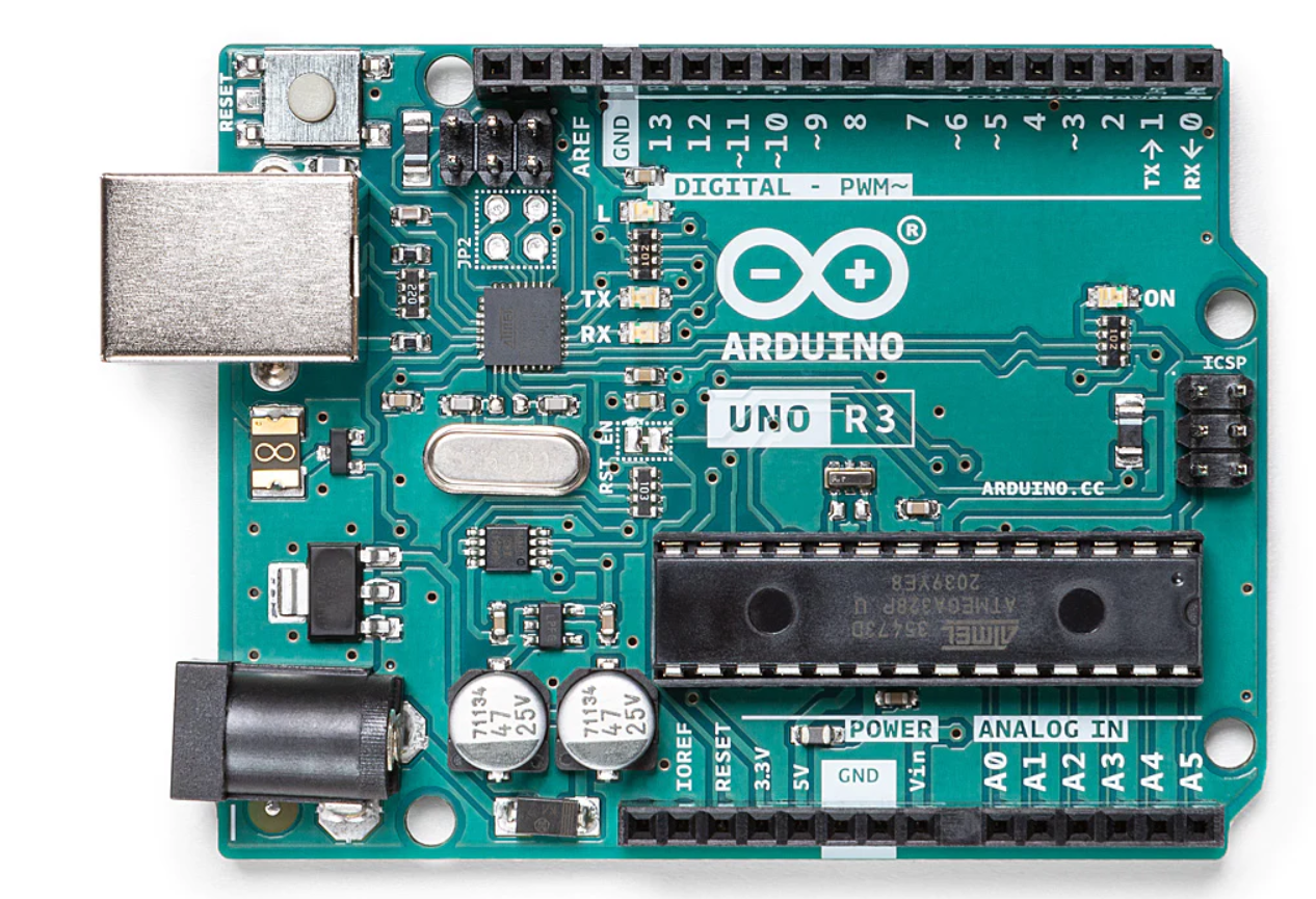
- Arduino Uno : Arduino Uno is a microcontroller from the Arduino Family. It was developed by Arduino. cc and is based on the Microchip ATmega328P microcontroller. Uno has 20 I/O pins, 6 are analog pins and 14 are digital pins.

For more details, pinout and datasheet, you can visit : https://docs.arduino.cc/hardware/uno-rev3
- Relay module: Relay is a programmable switch it can be controlled through any board like Arduino
- 2 X ultrasonic sensor(HC-SR04): It is a SONAR-based distance measurement sensor. It provides excellent non-contact range detection from 2 cm to 400 cm with high accuracy and reliable readings.
- 16 X 2 LCD: An LCD is an electronic display module that uses liquid crystal. The 16×2 translates o a display of 16 characters per line in 2 such lines. In this LCD each character is displayed in a 5×7 pixel matrix.
Software Requirements
- Arduino Ide :
Arduino IDE (Integrated development environment) is software that is used to dump the program into boards. Arduino- IDE's major use is to build electronics-related projects. Arduino is an open-source platform simple and easy-to-understand platform for coding.
HOW TO INSTALL ARDUINO IDE CLICK ON THE LINK :
https://techieyantechnologies.com/2022/10/installation-of-arduino-ide/
Block diagram
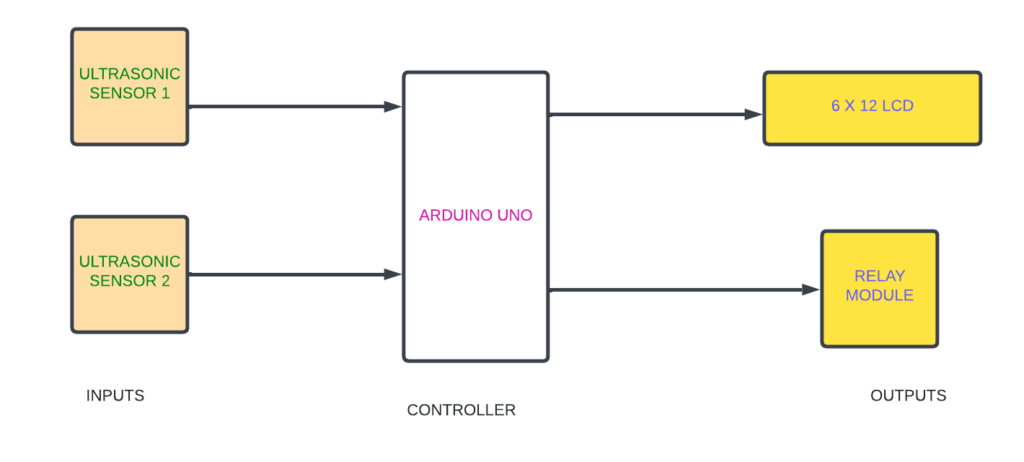
In the following block diagram of visitor monitoring system two ultrasonic sensors are used as input and Arduino Uno is used as a controller which is used to control input and output devices with the help of code.

Flow Chart
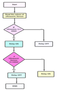
A flowchart is a diagram that shows a process’s steps in proper order. Similarly, the following flowchart talks about the steps involved in this visitor counter system project and the sequential flow of the code. So, as it starts, first the ultrasonic sensor1 checks whether anyone has entered a room. If any has entered the room the relay will turn on else the relay will be off. if a person has left the room then this will be calculated by the 2 ultrasonic sensors, as the relay will be off. the values will be displayed on LCD.
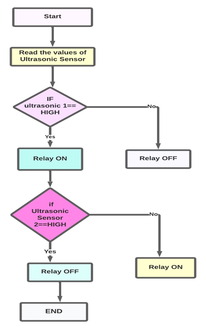
*website used to make Flow Chart and Block Diagram : https://www.lucidchart.com/pages/
Pin Wiring
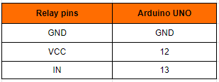
Relay
Relay has 3 pins
The following pin connection is the connection of the relay with the Arduino Uno. The relay has 3 pins, GND is connected to the GND of Arduino Uno, Vcc is connected to the D12 of Arduino Uno, and the IN pin is connected to 13 pins of Arduino Uno.
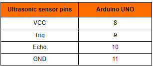
Ultrasonic Sensor
Ultrasonic sensor has 4 pins
The following pin connection is about the connection of ultrasonic pins with Arduino Nano. The Ultrasonic Sensor has 4 pins Vcc, Trig(Trigger), Echo & Ground. Vcc pin of ultrasonic is connected to 5V of Arduino Nano, Trig is connected to D3, Echo is connected to D2, and Ground(GND) is connected to GND
LCD
The LCD has 16 pins. VSS is connected to the GND of the Arduino Uno.VCC is connected to the 5v of the Arduino Uno.VEE is connected to the potentiometer of the Arduino Uno.RS is connected to the A0 pin of the Arduino Uno.R/W is connected to the GND of the Arduino Uno. E is connected to the 12th pin of the Arduino Uno.DB4is connected to the A2 pin of the Arduino Uno.DB5 is connected to the A3pin of the Arduino Uno.DB6 is connected toA4 of the Arduino Uno.DB7 is connected toA5 of the Arduino Uno.
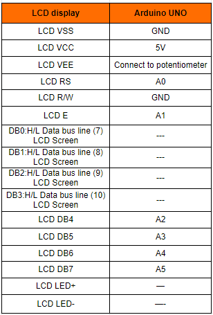
Potentiometer
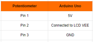
Potentiometer has 3pins GND, VCC, and output. where Pin1 is connected to the 5V of the Arduino Uno. Pin2 is Connected to LCD VEE. Pin 3 is connected to the GND of the Arduino Uno.

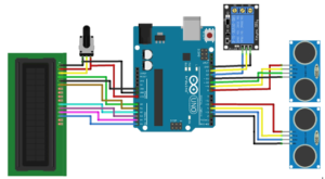
Circuit diagram
Note: Make sure to take proper precautions while connecting the components.

Working
The next step in visitor counter and monitoring system after setting up the connection is to upload code to Arduino Uno and power it. When the system is turned on, If a person has left the room then also the relay will be turned off. This will be calculated by 2 ultrasonic sensors that continue to read the values of the ultrasonic sensor. If any person is detected then the relay will be turned on else the relay will be off.
Conclusion
Thus we conclude that the visitor counter system is very helpful in everyone's life, it is used to reduce electric consumption, and also save electricity from getting wasted and one has to not worry about the on and off electrical appliances.
Working Code
 #include <LiquidCrystal.h>                             //Using the Arduino as the controller device, the library Allows communication with liquid crystal displays (LCDs).
 LiquidCrystal lcd(13,12,A2,A3,A4,A5);                  // initialize the library by associating any needed LCD interface pin with arduino uno
#define e_s1 3                                          //ultasonic echo pin is connected to pin 2 of Arduino
#define t_s1 4                                          //ultasonic trigger pin is connected to pin 2 of Arduino
#define e_s2 10                                         //ultasonic echo pin is connected to pin 2 of Arduino
#define t_s2 9                                          //ultasonic echo pin is connected to pin 2 of Arduino
int relay = 12;                                         // relay pin is connected to pin 12 of arduino
long dis_a=0,dis_b=0;                                   //integer dis is created for store the value from ultrasonic sensor
int flag1=0, flag2=0;                                   //integer flag is created to give the value from ultrasonic sensor
int person = 0;
//function to read untrasonic values
void ultra_read(int pin_t,int pin_e,long &ultra_time){
long time;
pinMode(pin_t,OUTPUT);
pinMode(pin_e,INPUT);
digitalWrite(pin_t,LOW);
delayMicroseconds(2);
digitalWrite(pin_t,HIGH);
delayMicroseconds(10);
time=pulseIn (pin_e,HIGH);
ultra_time =  time / 29 / 2;
}
void setup(){
  Serial.begin(9600);                                     // initialize serial communication at 9600 bits per second:
  pinMode(relay, OUTPUT);                                 // select relay pin as a output pin
  pinMode(13, OUTPUT);                                    // select ultrasonic pin as a output pin
  pinMode(2, OUTPUT);                                     // select ultrasonic pin as a output pin
  pinMode(5, OUTPUT);                                     // select ultrasonic pin as a output pin
  pinMode(8, OUTPUT);                                     // select ultrasonic pin as a output pin
  pinMode(11, OUTPUT);                                    // select ultrasonic pin as a output pin
  lcd.begin(16, 2);
  lcd.setCursor(0,0);
  lcd.print("     Welcome    ");
  Serial.print("hello");
  delay(1000);                                             // Waiting for a while
  lcd.clear();
}
void loop(){
  digitalWrite(13,HIGH);
  digitalWrite(5,HIGH);
  digitalWrite(2,LOW);
  digitalWrite(8,HIGH);
  digitalWrite(11,LOW);
//*
ultra_read(t_s1,e_s1,dis_a);delay(30);                       //reading the value of 1st-ultrasonic sensor
ultra_read(t_s2,e_s2,dis_b);delay(30);                       //reading the value of 1st-ultrasonic sensor
//*
  Serial.print("da:");
  Serial.println(dis_a);
  Serial.print("db:");
  Serial.println(dis_b);
if(dis_a<90 && flag1==0){                                      //giving the codition to ultasonic sensor
  flag1=1;                                                     // intializing flag1 value as 1
if(flag2==0){                                                  //Applying the condition
  person = person+1;                                           // adding the number of persons entered in a room
   }
}
if(dis_b<90 && flag2==0){                                      //giving the codition to ultasonic sensor
  flag2=1;                                                     // intializing flag2 value as 1
if(flag1==0){                                                  //Applying the condition
  person = person-1;                                           // detecting the number of persons left the room
  }
}
if(dis_a>90 && dis_b>90 && flag1==1 && flag2==1){              //comparing 1st ultrasonic with 2nd ultrasonic sensor
  flag1=0, flag2=0;
  delay(1000);
}
//displaying the values on LCD
  lcd.setCursor(0, 0);
  lcd.print("Have Person: ");
  lcd.print(person);
  lcd.print("  ");
  lcd.setCursor(0,1);
  lcd.print("Light is ");
  lcd.clear();
   if( person>0 ){
    digitalWrite(relay,LOW);
    lcd.print("On ");
 }
else{
  digitalWrite(relay,HIGH );                                      //turn off the relay
  lcd.print("Off");}
}
Click here to download the entire code for the visitor counter system.
If You Face Any Issue Feel Free To Contact us Any Time.


Need the source code or help?
Contact us for model weights, datasets, or guidance on running this project.