
Vehicle Speed Detection and Over-Speed Control System
Abstract
These days, excessive speed and reckless driving are to blame for a large number of accidents. Even though there are numerous rules and provisions against excessive speeding, people nonetheless drive their cars at these rates. We created a project, vehicle speed control system that measures the speed of the car and sets a speed limit in order to prevent accidents brought on by overspeed. The distance between obstacles is determined using two infrared sensors. When an obstruction moves in front of the IR1 sensor, it becomes active. When the obstruction moves through the IR2 sensor, it becomes active. Here in this vehicle speed control system project, the IR sensors provide us the amount of time it takes for an object to go from the IR1 to the IR2 sensor, which allows us to determine the vehicle’s speed.
Nowadays, everyone is using vehicles and these days road accidents are probably occurring, and it leads to death. The main reasons for road accidents are rash driving and over-speeding. It is risky for another person also. To avoid this kind of accident, we have several rules and regulations but many people do not follow the traffic rules and it leads to accidents. To avoid that, we are designing a project for controlling speed.
Introduction
Here, vehicle speed control system project is built to avoid road accidents that are happening because of rash driving and over-speeding. This project is built with sensors and motors to control the speed of the vehicle. In this project, 2 IR sensors are used to detect the speed of the obstacle vehicle when the object/vehicle is passed from IR sensor 1 to IR sensor 2. They get activated when the vehicle passes through them. When the vehicle’s speed is increased, the DC motor gets activated by the predetermined threshold, the buzzer sounds, and the relay and motor control the vehicle’s speed. When the motor is on, vehicle speed reduces to avoid any kind of accident. If the vehicle’s speed exceeds a predetermined threshold, the buzzer sounds and the relay turns on the dc motor. In this vehicle speed control system project, the motor is used to control the vehicle’s speed. Because the power supplied by the Arduino is insufficient for the dc motor, it requires an extra power supply. When the motor is turned on, it slows the vehicle’s speed, allowing us to regulate the vehicles over speed
Components Required
Hardware Requirements
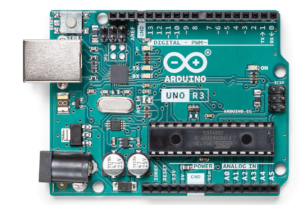
- Arduino Uno :
Arduino Uno is a microcontroller from the Arduino Family. It was developed by Arduino. cc and is based on the Microchip ATmega328P microcontroller. Uno has 20 I/O pins, 6 are analog pins and 14 are digital pins.
For more details, pinout and datasheet, you can visit : https://docs.arduino.cc/hardware/uno-rev3
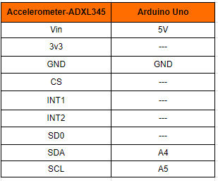
- Accelerometer-ADXL345
- sensors-HW-201: it is an electronic device that measures and detects infrared radiation in its surrounding environment.
- Buzzer-MH-FMD: The buzzer is an electric-sounding device that generates sounds.
- 5V Relay: it is an automated switch that is used in automated circuits.
- DC motor: A device that converts direct current into mechanical energy is known as a DC motor.
Software Requirements
- Arduino Ide : Arduino IDE (Integrated development environment) is software that is used to dump the program into boards. Arduino- IDE’s major use is to build electronics-related projects. Arduino is an open-source platform simple and easy-to-understand platform for coding.
HOW TO INSTALL ARDUINO IDE CLICK ON THE LINK :
https://techieyantechnologies.com/2022/10/installation-of-arduino-ide/
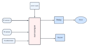
Block diagram
In these block diagrams, we are giving IR sensors and an accelerometer as input to Arduino and power supply to it, and a buzzer and motors are output for Arduino.
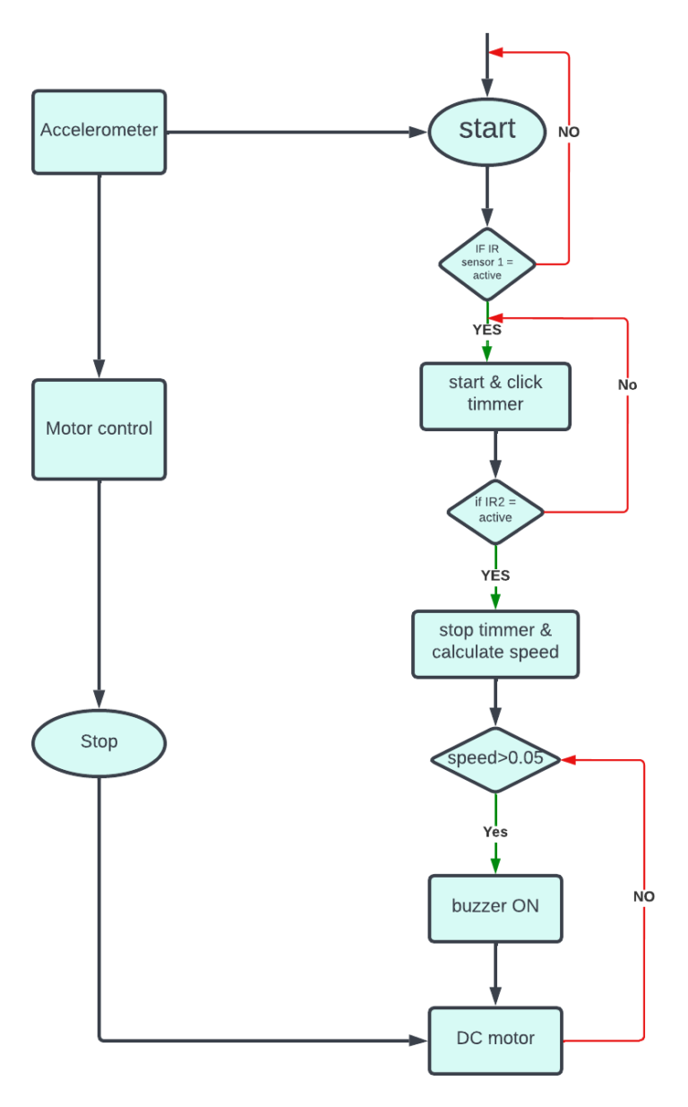
Flow Chart
The above flowchart is indicating us that when IR sensor 1 is get activated it gets starts and clicks the timmer and it stops when IR sensor 2 is activated and calculates time if of object speed is greater than 0.05 buzzer gets on and DC motor active
*website used to make Flow Chart and Block Diagram : https://www.lucidchart.com/pages/
Connections and Pins:
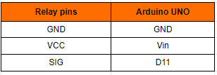
Relay
Relay has 3 pins
The following pin connection is the connection of the relay with the Arduino Uno. The relay has 3 pins, GND is connected to the GND of Arduino Uno, Vcc is connected to D12 of Arduino Uno, and the pin is connected to the 13th pin of Arduino Uno.
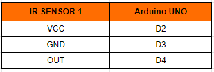
Sensor 1
IR sensor 1 has 3 pins. the VCC is connected to the D2 of the Arduino Uno. the GND is connected to the D3 of the Arduino Uno. the OUT is connected to the D2 of the Arduino Uno.
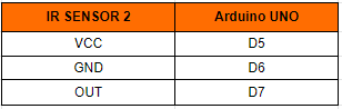
Sensor 2
IR sensor 2 has 3 pins. The VCC is connected to the D5 of the Arduino Uno. The GND is connected to the D6 of the Arduino Uno. The OUT is connected to the D7 of the Arduino Uno.
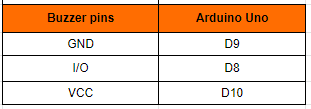
Buzzer
The buzzer has 3 pins, the GND is connected to D9 of Arduino Uno. The I/O pin is connected to theD8 Arduino Uno. the VCC pin is connected to the D10 of the Arduino Uno.
Accelerometer
Accelerometer-ADXL345 has 9 pins. the Vi connected to 5v of the Arduino Uno. the GND connected to the GND of the Arduino Uno. the SDA connected to the A4 of the Arduino Uno. the SCl connected to the A5of the Arduino Uno.
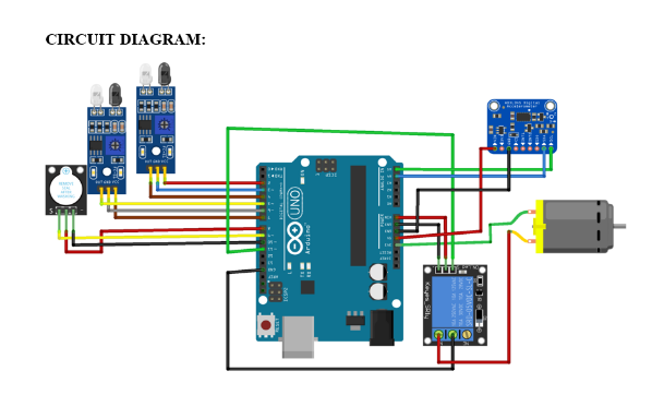
Circuit diagram
Note: Make sure to take proper precautions while connecting the components.
Working
The next step after setting up the connection is to upload code to Arduino Uno and power it. When the system is turned on, If a person has left the room then also the relay will be turned off. This will be calculated by 2 ultrasonic sensors that continue to read the values of the ultrasonic sensor. If any person is detected then the relay will be turned on else the relay will be off.
Conclusion
Thus we conclude that the visitor counter is very helpful in everyone’s life, it is used to reduce electric consumption, and also save electricity from getting wasted. and one has to not worry about the on and off electrical appliances.
Working Code
#include <Wire.h>               //Using the Arduino as the controller device,the library enables to communicate with I2C devices

int ADXL345 = 0x53;             //address of an ADXL
int X_out, Y_out, Z_out;
#define IR1 4                   //ir sensor pin connecetd to pin 4of Arduino Nano
#define IR2 5                   //ir sensor in connecetd to pin 5 of Arduino Nano
#define buzzer 9                 //buzzer pin connecetd to pin 9 of Arduino Nano
#define relay 11                //realy pin connecetd to pin 6 of Arduino Nano
int i=0;                        //integer i is created to store the value of ir sensor
int p =0;
int q = 1;
float s ;


void setup ()
{   pinMode (IR1,INPUT);          //Set ir as INPUT device
    pinMode (2,OUTPUT);
    pinMode (3,OUTPUT);
    pinMode (IR2,INPUT);           //Set ir as INPUT device
    pinMode (6,OUTPUT);
    pinMode (7,OUTPUT);
    pinMode (buzzer,OUTPUT);       //Set BUZZER as OUTPUT device
    pinMode (8,OUTPUT);
    pinMode (10,OUTPUT);
    pinMode(relay,OUTPUT);        //Set relay as OUTPUT device
    Serial.begin(9600);           // Initiate a serial communication with baud rate of 9600
    Wire.begin();

    digitalWrite(relay,HIGH);

  Wire.beginTransmission(ADXL345);
  Wire.write(0x2D);                                 //talk to POWER_CTL Register - 0x2D

  Wire.write(8);                                   // Bit D3 High for measuring enable (8dec -> 0000 1000 binary)
  Wire.endTransmission();
  delay(10);

}
void loop()
    {

    digitalWrite (2,HIGH);
    digitalWrite (7,HIGH);
    digitalWrite (8,HIGH);
    digitalWrite(10,LOW);
    digitalWrite(3,LOW);
    digitalWrite(6,LOW);
    int I1 = digitalRead(IR1);
    int I2 = digitalRead(IR2);

  Wire.beginTransmission(ADXL345);
  Wire.write(0x32);
  Wire.endTransmission(false);
  Wire.requestFrom(ADXL345, 6, true);

  X_out = ( Wire.read() | Wire.read() << 8);
  Y_out = ( Wire.read() | Wire.read() << 8);
  Z_out = ( Wire.read() | Wire.read() << 8);

  Serial.print(X_out);
  Serial.print(" ");
  Serial.print(Y_out);
  Serial.print(" ");
  Serial.println(Z_out);
  delay(100);


   while(((I1==0)||(i==!0))&&(q==1))   //when  ir sensor values
   {

    int I1=digitalRead(IR1);           //storing ir sensor values in I1
    int I2=digitalRead(IR2);           //storing ir sensor values in I2


    delay(10);
    i = i+1;                          // incrementing i value
    p=p+1   ;                         // incrementing i value to calculate time
    Serial.println(i);                // displaying the i value on serial monitor
    if (I2 == 0)                      //if vehicle pass through 2 ir sensor
    {
      i = 0;
      q=0;
      Serial.println("Exit");

 Serial.print("Time in Sec: ");
 Serial.print(p*0.01);                //formula to calculatr time

 s = 0.15/(p*0.01);                   //formula to calculate speed
    Serial.println("Speed: ");        //displaying the values of speed on serial monitor
Serial.print(s);

       }
   }

    if(s > 0.100)                      // if speed of the vehicle is more
    {
        tone(buzzer,1000,100);        // turn on the buzzer
        digitalWrite(relay,LOW);      //turn on the relay

        }

    else
      {
        noTone (buzzer);              // turn off the buzzer
        digitalWrite(relay,HIGH);     // turn off the relay

            }

    }
If You Face Any Issue Feel Free To Contact us Any Time.