
Overview
Smart Surveillance System

Abstract
Surveillance systems have been an essential part of industries, factories, organisations and homes. They actually provide additional assistance in the work of security personnel because of information storing capabilities. In addition, they also provide extreme assistance in various automation processes of chemical industries where continuous monitoring of certain chemical reactions is mandatory. The installation of such systems at the cost of a meagre amount is the need of hour for controlling theft and avoiding any disaster. The objective of this project is to create a surveillance system. Security is the major and utmost concern when it comes to confidential matters. This project is the prototype of the surveillance system that can be used almost everywhere it's needed instead of an expensive surveillance system. The camera will be monitoring the place as the PIR sensor detects the motion. If the motion is detected, then the buzzer gets activated and an alert message is sent to the user with the help of the GSM module.Introduction
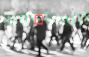
In today's world, where everyone wants to keep their valuables safe and secure, video surveillance for observing a particular area has become the need of the hour. To address this problem, we have come up with a smart surveillance system for certain places like bank vaults, homes where human presence is not available. At such places, it is not worth continuously monitoring the area with the cameras.Conducting close observation or monitoring a place can be termed surveillance. When something is important, then to monitor its presence, one must keep track of it, and this can be achieved by implementing a surveillance system. This system can be advanced with further modifications. In existing systems, surveillance cameras needed to be monitored by a man, and the camera was also very costly. In the case of the proposed system, video analysis is done by software. Furthermore, the size of the footage is reduced as the motion sensor only records when a motion is detected. These surveillance cameras are now being replaced with these cameras, where there is an additional feature of face recognition. There are many other technologies that can be integrated with surveillance cameras to make them more accurate and efficient.Components Required
Hardware Requirements- Arduino Uno : Arduino Uno is a microcontroller from the Arduino Family. It was developed by Arduino. cc and is based on the Microchip ATmega328P microcontroller. Uno has 20 I/O pins, of which 6 are analog and 14 are digital pins.
 For more details, pinout and datasheet, you can visit : https://docs.arduino.cc/hardware/uno-rev3
- PIR sensor: Passive Infrared sensor is an electronic device. It is used to detect the heat energy in the surroundings.
- Buzzer: An Audio Signalling Device. Buzzers can be mechanical, electromechanical, or piezoelectric. It produces an alarming sound when triggered. Used in various applications like Game buzzers, Alarm Buzzers, Trains, etc.
- GSM module: global system for mobile communication (GSM) module is used to send and receive data/messages.
- Camera: it records the visual image in the form of a video.
- Arduino Ide : Arduino IDE (Integrated development environment) is software that is used to dump the program into boards. Arduino- IDE's major use is to build electronics-related projects. Arduino is an open-source platform simple and easy-to-understand platform for coding.
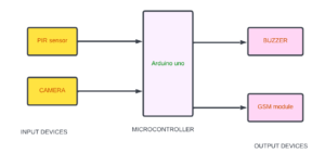
Block diagram
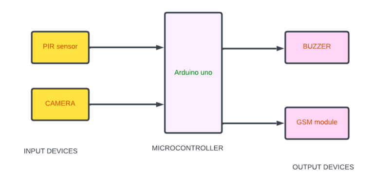
In the following block diagram PIR sensor and camera are the input devices. The GSM module and buzzer are the output devices. Arduino Uno is the microcontroller.
Flow Chart
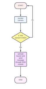
Flow chart is the diagrammatic representation of an algorithm(or code flow). If the PIR sensor is high(or activated) an alert message will be sent and the buzzer will be activated. *website used to make Flow Chart and Block Diagram : https://www.lucidchart.com/pages/
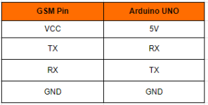
Pin Wiring
GSM Module The VCC pin of the GSM module is connected to the 5v pin of the Arduino. The TX pin of the GSM module is connected to the RX pin of the Arduino. The RX pin of the GSM module is connected to the TX pin of the Arduino. The GND pin of the GSM module is connected to the GND pin of the Arduino.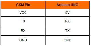 PIR Sensor
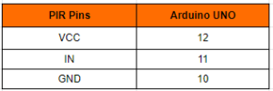
The VCC pin of the PIR Sensor is connected to the 5th pin of the Arduino. The GND pin of the PIR Sensor is connected to the 6th pin of the Arduino. The OUT pin of the PIR Sensor is connected to the 7th pin of the Arduino.
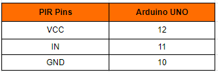
PIR Sensor
The VCC pin of the PIR Sensor is connected to the 5th pin of the Arduino. The GND pin of the PIR Sensor is connected to the 6th pin of the Arduino. The OUT pin of the PIR Sensor is connected to the 7th pin of the Arduino.
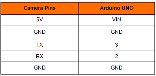
 Camera Pins
The 5v pin of the camera is connected to the VIN pin of the Arduino. The GND pin of the camera is connected to the GND pin of the Arduino. The TX pin of the camera is connected to the 3rd pin of the Arduino. The RX pin of the camera is connected to the 2nd pin of the Arduino. The GND pin of the camera is connected to the GND pin of the Arduino.
Camera Pins
The 5v pin of the camera is connected to the VIN pin of the Arduino. The GND pin of the camera is connected to the GND pin of the Arduino. The TX pin of the camera is connected to the 3rd pin of the Arduino. The RX pin of the camera is connected to the 2nd pin of the Arduino. The GND pin of the camera is connected to the GND pin of the Arduino.
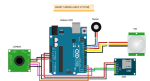
Circuit diagram
Note: make sure to take proper precautions while connecting the components.
Working
The camera is used to monitor the surroundings. Once the PIR sensor detects the motion. Once the motion is detected by the PIR sensor, the buzzer will be activated and an alert will be sent to the authorities with the help of the GSM module stating an unauthorised person has tried to get in.Conclusion
Hence, the smart surveillance system using the GSM module is successfully built. In the future, we can modify the project and implement it with different technologies and an android application with the help of iot.Working Code


Need the source code or help?
Contact us for model weights, datasets, or guidance on running this project.