
Smart Security System Using RFID and GSM
Abstract

In this modern world, everyone wants their belongings to be safe and secure. People want to monitor their homes even when they are away from the place where they are. They want to monitor the home environment being miles away. So this system is proposed for all these purposes. The main aim of smart security system project is to make a security system based on RFID and GSM modules. Here, in smart security system using RFID project, the first IR sensor senses the presence of the person and activates the system. If the RFID card is authentic, then the solenoid lock will be opened and there will be the person’s name displayed on the LCD and the login and logout of the user will be tracked. If the RFID card is not authentic, then the solenoid lock will remain locked and a buzzer will be activated. On the LCD, a message will pop up stating “No user found” and a message will be sent to the authorities with the help of the GSM module stating an unauthorized person has tried to get in. These systems are mostly used in offices, schools, industrial places, etc.
Introduction
“Security” is termed as the state of being safe. The purpose of security is to prevent fraud and theft in any domain. Security systems have been advancing over the past few years due to technological advancements. To design smart security system project, A three-level security system can be developed with the help of RFID and GSM modules. The use of radio signals to identify, track, and sort objects is a non-contact, automatic identification method known as radio frequency identification (RFID).The need for securing homes exists since ancient days. Techniques for protecting the households are door locks, barred windows. etc. Nowadays, security systems are all automated which can detect undesired situations occurring at home while the owners are away. RFID has many applications, such as Kiosks that use RFID to manage resources. It can be implemented in library systems, tool tracking, attendee tracking, etc. The GSM module is a global system for mobile communication which is designed to monitor SMS (short messaging service) through wireless radiation. The GSM module has many compactable features such as voice clarity, international roaming, RTC(real time clock), etc.
Components Required
Hardware Requirements
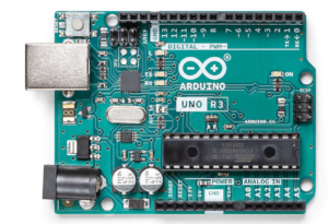
- Arduino Uno : Arduino Uno is a microcontroller from the Arduino Family. It was developed by Arduino. cc and is based on the Microchip ATmega328P microcontroller. Uno has 20 I/O pins, of which 6 are analog and 14 are digital pins.
For more details, pinout and datasheet, you can visit : https://docs.arduino.cc/hardware/uno-rev3
- RFID module(tag, reader): it stands for radio frequency identification reader. It is used to read the information from an RFID tag.
- GSM module: global system for mobile communication (GSM) module is used to send and receive data/messages.
- Buzzer: An Audio Signalling Device. Buzzers can be mechanical, electromechanical, or piezoelectric. It produces an alarming sound when triggered. Used in various applications like Game buzzers, Alarm Buzzers, Trains, etc.
- Ir sensor: It is an electronic device that emits infrared rays
- Solenoid lock: the solenoid lock is used to lock and unlock through electrical power.
- Relay: used to operate AC devices like lights, fans, etc. it is basically a switch. It works on the principle of electromagnetism. It takes DC power as input and gives out AC power.
- LCD: LCD (Liquid Crystal Display) is a type of flat panel display used to print values.
Software Requirements
- Arduino Ide : Arduino IDE (Integrated development environment) is software that is used to dump the program into boards. Arduino- IDE’s major use is to build electronics-related projects. Arduino is an open-source platform simple and easy-to-understand platform for coding.
HOW TO INSTALL ARDUINO IDE CLICK ON THE LINK :
https://techieyantechnologies.com/2022/10/installation-of-arduino-ide/
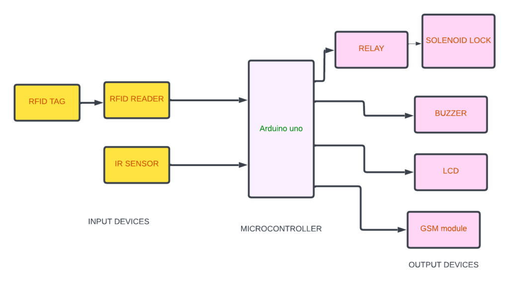
Block diagram
In the following block diagram IR sensor and the relay are input devices. Buzzer, LCD, and solenoid lock are output devices. Arduino Uno is the microcontroller where input and output devices are integrated.
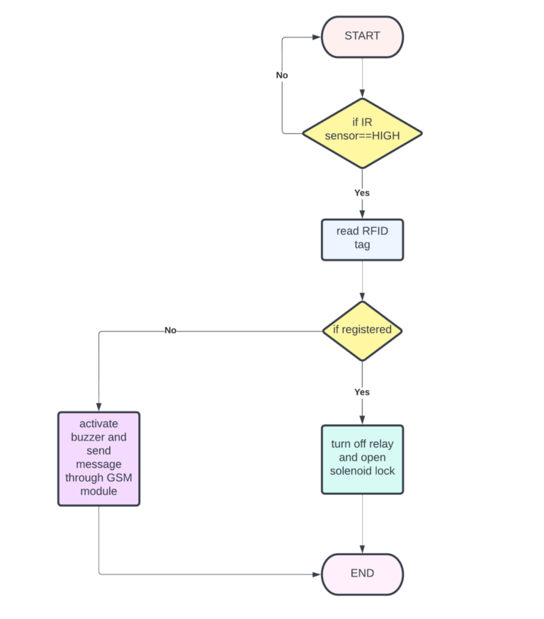
Flow Chart
First, if the IR sensor is activated then it starts reading the RFID tag. If the RFID tag is registered/authentic then the lock will be opened, else the buzzer will be activated and an alert message will be sent to the user.
*website used to make Flow Chart and Block Diagram : https://www.lucidchart.com/pages/
Pin Wiring
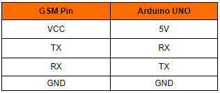
GSM Module
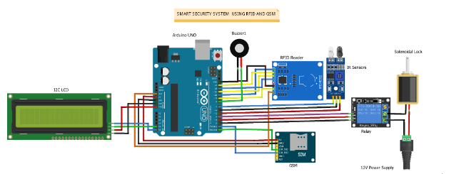
The VCC pin of the GSM module is connected to the 5v pin of the Arduino. The TX pin of the GSM module is connected to the RX pin of the Arduino. The RX pin of the GSM module is connected to the TX pin of the Arduino. The GND pin of the GSM module is connected to the GND pin of the Arduino.
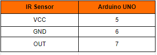
IR Sensor
The VCC pin of the IR Sensor is connected to the 5th pin of the Arduino. The GND pin of the IR Sensor is connected to the 6th pin of the Arduino. The OUT pin of the IR Sensor is connected to the 7th pin of the Arduino.
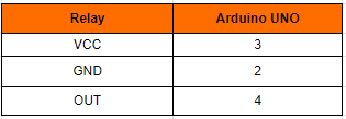
Relay
The VCC pin of the relay is connected to the 3rd pin of the Arduino. The OUT pin of the relay is connected to the 4th pin of the Arduino. The GND pin of the relay is connected to the 2nd pin of the Arduino.
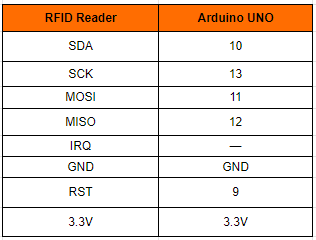
RFID Reader
The SDA pin of the RFID Reader is connected to the 10th pin of the Arduino. The SCK pin of the RFID Reader is connected to the 13th pin of the Arduino. The MOSI pin of the RFID Reader is connected to the 11th pin of the Arduino.
The MISO pin of the RFID Reader is connected to the 12th pin of the Arduino. The IRO pin of the RFID Reader is not connected to any pin of the Arduino. The GND pin of the RFID Reader is connected to the GND pin of the Arduino. The RST pin of the RFID Reader is connected to the pin 9th of the Arduino. The 3.3v pin of the RFID Reader is connected to the 3.3v pin of the Arduino.
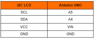
12c LCD
The SCL pin of the I2c LCD is connected to the A5 pin of the Arduino. The SDA pin of the I2c LCD is connected to the A4 pin of the Arduino. The VCC pin of the I2c LCD is connected to the Vin pin of the Arduino. The GND pin of the I2c LCD is connected to the GND pin of the Arduino.
Circuit diagram
Note: make sure to take proper precautions while connecting the components.
Working
The IR sensor detects the presence of the person. If the person puts the RFID tag on the RFID reader it will recognize the details of the person. If the details are recognized the Solenoid lock will open and the person will be able to enter. If the details are unrecognized the solenoid will be locked and an alert will be sent to the authorities with the help of the GSM module stating an unauthorized person has tried to get in.
Conclusion
Hence, the smart security system using RFID and GSM modules is successfully built. It is very useful in offices, schools, industries, and e.t.c.
Working Code
Click Here to download the code of smart security system using RFID
If You Face Any Issue Feel Free To Contact us Any Time.