
Overview
Smart Irrigation System Using GSM Module
Abstract
In this project, an automatic plant watering system based on Arduino has been developed. Multiple sensors are used like soil moisture sensors, which assist in the auto-detection of water requisition in the soil. The DHT11 is a humidity and temperature sensor that measures air temperature and humidity. Soil relative humidity, air temperature, soil temperature, and air relative humidity are all measured and the gsm module is used which will send a message to mobile to get an alert. A Servo motor is used to insert the seed into the soil. Through this project, one can improve the plan's crop quality and health by increasing the performance measure. The development of an Automatic Plant Irrigation System which is capable of detecting moisture loss in the soil is proposed in this project. It specifically uses the Soil Moisture Sensor to detect water content levels within the soil and provide appropriate system responses based on the detected conditionIntroduction
Agriculture is the primary source of the Indian economy. The majority of clean water resources are used in agriculture. This Automatic Plant Irrigation System project aims to develop an automated irrigation mechanism that turns the pumping motor ON and OFF by itself and an automatic message is generated. Most farmers around the world struggle to keep their crops watered properly, but they are powerless to do so. This system will allow farmers to irrigate their land without the need for additional manpower. The system is user-friendly and has simple circuitry which will make the user operate the system easily. It is only necessary to connect the pump to the circuit and connect the circuit and sensors completely. The system will start to work immediately after powering up and will not require any triggers. The goal of the project is to use sensors to detect soil dryness and provide appropriate water to the plants whenever it is necessary and add seeds into the soil.Components Required
Hardware Requirements- Arduino Uno : Arduino Uno is a microcontroller from the Arduino Family. It was developed by Arduino. cc and is based on the Microchip ATmega328P microcontroller. Uno has 20 I/O pins, of which 6 are analog and 14 are digital pins.
 For more details, pinout and datasheet, you can visit : https://docs.arduino.cc/hardware/uno-rev3
- Dht11: Digital Humidity and Temperature (Dht) sensor is used to find the amount of humidity present in the air.
- Soil moisture sensor: A soil moisture sensor is used to find the amount of moisture present in the soil.
- Motor: It is an electric machine that converts electrical energy into mechanical energy.
- Relay: used to operate AC devices like lights, fans, etc. it is basically a switch. It works on the principle of electromagnetism. It takes DC power as input and gives out AC power.
- GSM module: global system for mobile communication (GSM) module is used to send and receive data/messages.
- Servo motor (90): It is an electromechanical device used for rotatory purposes with precise precisions.
- Arduino Ide : Arduino IDE (Integrated development environment) is software that is used to dump the program into boards. Arduino- IDE's major use is to build electronics-related projects. Arduino is an open-source platform simple and easy-to-understand platform for coding.
Block diagram
The block diagram describes the relationship between the input devices and output devices. Here in this case input devices are a DH11 sensor, a soil moisture sensor and that sends the information to Arduino where the output is transmitted to the specific devices such as a relay to turn the motor on and off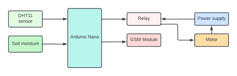
Flow Chart
First the data is taken from the DHT sensor and soil moisture sensor. If the data is given by the sensors then the servo motor will be activated else it will not be activated and an alert message will be sent to the user.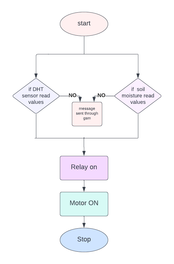 *website used to make Flow Chart and Block Diagram : https://www.lucidchart.com/pages/
Pin Wiring
DHT11 The VCC pin of the DHT11 sensor is connected to the 5v pin of the Arduino. The data pin of the DHT11 sensor is connected to the D4 pin of the Arduino. The NC pin of the DHT11 sensor is not connected to any pin of the Arduino. The GND pin of the DHT11 sensor is connected to the GND pin of the Arduino. GSM
The 5v pin of the GSM module is connected to the 5v pin of the Arduino. The GND pin of the GSM module is connected to the GND pin of the Arduino. The VCC pin of the GSM module is connected to the 5v pin of the Arduino. The SIM_TX pin of the GSM module is connected to the RXD pin of the Arduino. The SIM_RX pin of the GSM module is connected to the TXD pin of the Arduino. The GND pin of the GSM module is connected to the GND pin of the Arduino. The RST pin of the GSM module is not connected to any pin of the Arduino.
GSM
The 5v pin of the GSM module is connected to the 5v pin of the Arduino. The GND pin of the GSM module is connected to the GND pin of the Arduino. The VCC pin of the GSM module is connected to the 5v pin of the Arduino. The SIM_TX pin of the GSM module is connected to the RXD pin of the Arduino. The SIM_RX pin of the GSM module is connected to the TXD pin of the Arduino. The GND pin of the GSM module is connected to the GND pin of the Arduino. The RST pin of the GSM module is not connected to any pin of the Arduino.
 Soil Hygrometer Sensor
The VCC pin of the Soil hygrometer sensor is connected to the 5v pin of the Arduino. The A0 pin of the Soil hygrometer sensor is connected to the A7 pin of the Arduino. The D0 pin of the Soil hygrometer sensor is not connected to any pin of the Arduino. The GND pin of the Soil hygrometer sensor is connected to the GND pin of the Arduino.
Soil Hygrometer Sensor
The VCC pin of the Soil hygrometer sensor is connected to the 5v pin of the Arduino. The A0 pin of the Soil hygrometer sensor is connected to the A7 pin of the Arduino. The D0 pin of the Soil hygrometer sensor is not connected to any pin of the Arduino. The GND pin of the Soil hygrometer sensor is connected to the GND pin of the Arduino.
 Relay
The VCC pin of the relay is connected to the 5v pin of the Arduino. The IN pin of the relay is connected to the 3rd pin of the Arduino. The GND pin of the relay is connected to the GND pin of the Arduino.
Relay
The VCC pin of the relay is connected to the 5v pin of the Arduino. The IN pin of the relay is connected to the 3rd pin of the Arduino. The GND pin of the relay is connected to the GND pin of the Arduino.
 Servo SG90
servo SG90 has three wires. connect the orange/yellow wire of the servo to D7 of the Arduino. connect the red wire of the servo to the 5v of the Arduino. connect the brown wire of the servo to the GND pin of the Arduino.
Servo SG90
servo SG90 has three wires. connect the orange/yellow wire of the servo to D7 of the Arduino. connect the red wire of the servo to the 5v of the Arduino. connect the brown wire of the servo to the GND pin of the Arduino.
Circuit diagram
Note: make sure to take proper precautions while connecting the components.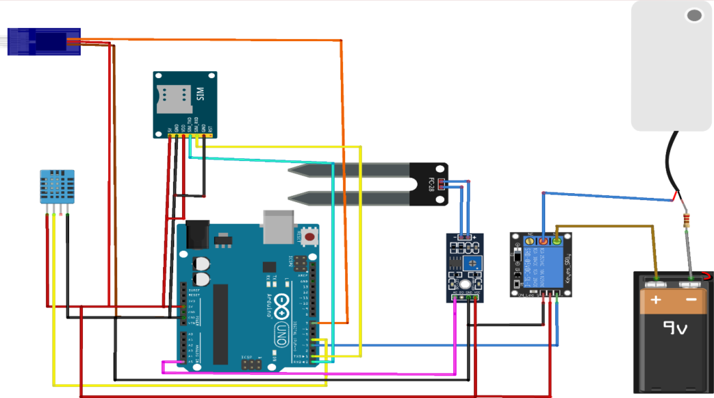
Working
The data taken by the humidity sensor and soil moisture sensor are first converted to electrical signals and sent analog data to the controller. When the amount of moisture in the soil and humidity decreases, the motor will be turned on immediately with the help of a relay so that the plants can get water. Activation and deactivation of the motor will depend on the values given by the sensors. If the sensors are unable to get or send data to the microcontroller then an alert message will be sent to the user.Conclusion
Hence, a smart irrigation system has been successfully built using the GSM module. With this system plant watering has been automated.Working Code


Need the source code or help?
Contact us for model weights, datasets, or guidance on running this project.