
Overview
Automatic railway gate controller and speed alerting system
Abstract
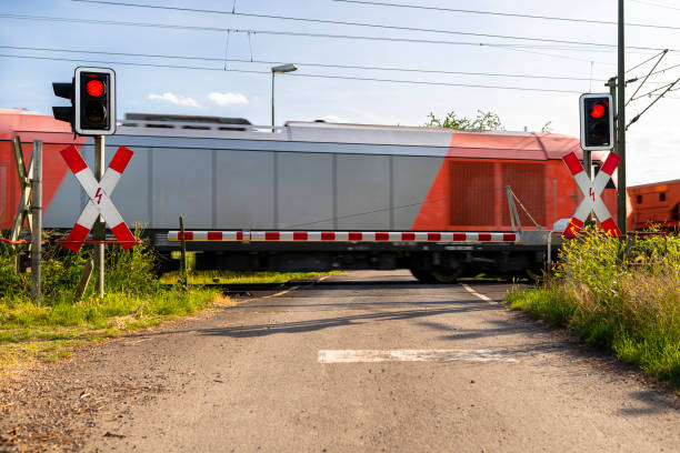
Over the previous five years, there have been about a million fatalities at unmanned railroad crossings worldwide. Due to their isolation and low volume of traffic, at least one-third of the railway crossings are unmanned. The Automatic Railway Gate Controller System using Arduino is focused on implementing systematic traffic control for both manned and unmanned railway gates. An Arduino Nano is used in the Automatic Railway Gate Control System Project to regulate the entire circuit. The railway gates are opened and closed by two servo motors. To detect a train's arrival or departure, a photodiode is used. The major goal is to shut the railway gates when the train gets close to prevent cars and other vehicles from crossing the track. The gates will automatically open to let vehicles pass as soon as the train moves further away from the railway crossing.Introduction
The main aim of this automatic railway gate controller project is to reduce train accidents at railway level crossings to a minimum. Level Crossing is a method that has been designed to prevent accidents. However, all level crossings were operated by people. The railway gate is opened or closed by the gate man who receives the information that a train is coming from the nearest railway station. In India, the majority of level crossings were operated. At all crossings, there are signals and barriers, and manual crossings must also include hand-held red and green signal flags. Indian Railways, on the other hand, wants to replace all unmanned crossings with manned crossings.Components Required
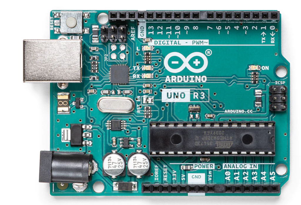
Hardware Requirements- Arduino Uno : Arduino Uno is a microcontroller from the Arduino Family. It was developed by Arduino. cc and is based on the Microchip ATmega328P microcontroller. Uno has 20 I/O pins, 6 are analog and 14 are digital pins.
 For more details, pinout and datasheet, you can visit : https://docs.arduino.cc/hardware/uno-rev3
- Servo motor (90)-2: servo SG90 is an electronic device used to rotate and push the object with precise angle. It is also known as a linear actuator. SG90 servo is a lightweight motor from which high output power is gained.
- Buzzer: An Audio Signalling Device. Buzzers can be mechanical, electromechanical, or piezoelectric. It produces an alarming sound when triggered. Used in various applications like a Game buzzers, Alarm Buzzers, Trains, etc.
- Tr led: the abbreviation of led is a light-emitting diode. it produces light.
- Photodiode: As the name suggests here photo means light and a diode means a semiconducting device. A photodiode is used to convert light energy into electrical energy.
- Lm358: Lm358 is used to amplify the power. It compares the voltage of input pins and generates the output required.
- Adapter: it is an electronic component that converts ac power to dc power. adapters should be selected according to the requirement of the application.
- Resistor: 10k,330 ohms: used to resist the excess current flowing into a device.
- Arduino Ide :Arduino IDE (Integrated development environment) is software that is used to dump the program into boards. Arduino- IDE's major use is to build electronics-related projects. Arduino is an open-source platform simple and easy-to-understand platform for coding.
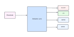
Block diagram
The block diagram of automatic railway gate controller describes the relationship between the input devices and output devices. Here, in this case, a photodiode is the input device that sends the information to the Arduino where the output is transmitted to specific devices such as a buzzer, servo, and led. These devices receive the information from the Arduino which is given by the input device.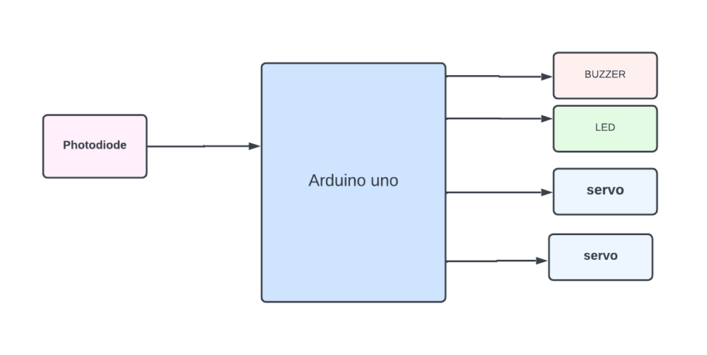
Flow Chart
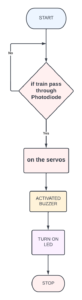
In the following flow chart, if the train passes through the photodiode then the servos, buzzer, and led will get activated else it will terminate. *website used to make Flow Chart and Block Diagram : https://www.lucidchart.com/pages/
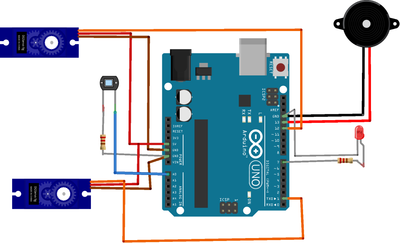
Pin Wiring
Buzzer The Buzzer has two pins, +5v and Ground. We connect +5v to pin 7 of Arduino Uno and Ground to GND(you can connect to any ground of Uno). Making pin 7 HIGH or LOW we can activate or deactivate the buzzer.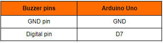 LED
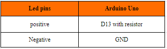
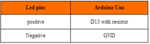
The LED has two pins, (positive)+v and Ground. We connect (positive)+v to pin 11 of Arduino Uno and Ground to GND(you can connect to any ground of Uno). Making pin 11 HIGH or LOW we can activate or deactivate the led.
LED
The LED has two pins, (positive)+v and Ground. We connect (positive)+v to pin 11 of Arduino Uno and Ground to GND(you can connect to any ground of Uno). Making pin 11 HIGH or LOW we can activate or deactivate the led.
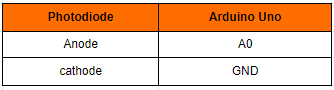
 Photodiode
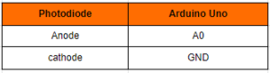
 has 2 pins: anode and cathode anode pin of the photodiode is connected to A0 of Arduino the cathode pin of the photodiode is connected to the GND of the Arduino.
Photodiode
Photodiode has 2 pins: anode and cathode anode pin of the photodiode is connected to A0 of Arduino the cathode pin of the photodiode is connected to the GND of the Arduino.
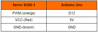
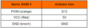
 Servo SG90 - 1
servo SG90 has three wires. connect the orange/yellow wire of the servo to the D12 of the Arduino. connect the red wire of the servo to the 5v of the Arduino. connect the brown wire of the servo to the GND pin of the Arduino.
Servo SG90 - 1
servo SG90 has three wires. connect the orange/yellow wire of the servo to the D12 of the Arduino. connect the red wire of the servo to the 5v of the Arduino. connect the brown wire of the servo to the GND pin of the Arduino.
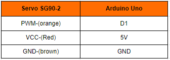
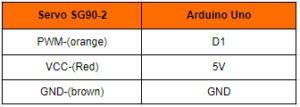
 Servo SG90 -2
servo SG90 has three wires. connect the orange/yellow wire of the servo to D1 of the Arduino. connect the red wire of the servo to the 5v of the Arduino. connect the brown wire of the servo to the GND pin of the Arduino.
Servo SG90 -2
servo SG90 has three wires. connect the orange/yellow wire of the servo to D1 of the Arduino. connect the red wire of the servo to the 5v of the Arduino. connect the brown wire of the servo to the GND pin of the Arduino.
Circuit diagram
Note: make sure to take proper precautions while connecting the components.
Working
In automatic railway gate controller system, if the train passes through the photodiode. it will show fluctuations in electric current produced by the photodiode. then the servo will be rotated by this the gates will automatically be down, gives an alarm through the buzzer and LED will be ON.Conclusion
Hence, we developed an Automatic railway gate controller and speed alerting system. it decreased the number of deaths caused by inappropriate gate-controlling systems. it is very accurate also.Working Code
#include<Servo.h>  //Using the Arduino as the controller device,the library enables to control the servo motor
Servo servo1;      //initialize a servo object to control a servo
Servo servo2;      //initialize a servo object to control a servo
int pos;           //initization position of servo motor
#define ir1 4      //ir sensor pin connecetd to pin 4 of Arduino uno
#define ir2 5      //ir sensor pin connecetd to pin 5 of Arduino uno
#define ir3 6      //ir sensor pin connecetd to pin 6 of Arduino uno
#define ir4 7      //ir sensor pin connecetd to pin 7 of Arduino uno
#define buzzer 13
int v1;           //integer v1 is created to store the value of ir1
int v2;           //integer v2 is created to store the value of ir2
int v3;           //integer v3 is created to store the value of ir3
int v4;           //integer v4 is created to store the value of ir4
void setup() {
  // put your setup code here, to run once:
   pinMode( ir1, INPUT);             //Set IR as INPUT device
   pinMode( ir2, INPUT);             //Set IR as INPUT device
   pinMode( ir3, INPUT);             //Set IR as INPUT device
   pinMode( ir4, INPUT);             //Set IR as INPUT device
   servo1.attach(3);                //Servo pin attached to 3 of arduino uno
   servo2.attach(2);
  }
void loop() {
  // put your main code here, to run repeatedly:
   v1 = digitalRead(ir1);      //read the value of ir sensor and store it in v1
   v2 = digitalRead(ir2);      //read the value of ir sensor and store it in v2
   v3 = digitalRead(ir3);      //read the value of ir sensor and store it in v3
   v4 = digitalRead(ir4);      //read the value of ir sensor and store it in v4
   if ((v1 == HIGH )&&(v2 == HIGH)){
    pinMode(buzzer,HIGH);
    for(pos=0;pos<=180;pos++){
    servo1.write(pos);
    servo2.write(pos);
    delay(15);
}
  delay(1000);
   }
  if ((v3== HIGH)&&(v4 == HIGH)){
      pinMode(buzzer,LOW);
      for(pos=180;pos>=0;pos--){
       servo1.write(pos);
       servo2.write(pos);
       delay(15);
}
  delay(1000);
   }
   }


Need the source code or help?
Contact us for model weights, datasets, or guidance on running this project.