
Overview
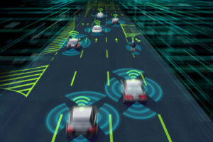
Adaptive Cruise Control of the Car
Abstract
Vehicles are primarily used for commuting requirements. Everyone else uses cars to travel around and complete daily tasks, go on vacation, visit another state, and commute to work. It has come to be accepted that this is how humans utilize vehicles. In fact, for many people, this is the sole instance of how they have ever used a vehicle. But there are a lot of other things your car may be used for that will surprise you. Vehicles play a major role in our day-to-day life for transportation, and many more various uses. According to the cause-wise research, over speeding was the primary factor in the majority of traffic accidents, accounting for 2,40,828 out of 4,03,116 incidents (59.7%), resulting in 87,050 fatalities and 2,28,274 injuries. The term Cruise Control refers to the idea of assisting drivers. The main aim of adaptive cruise control of the car project is to maintain a safe following distance from other vehicles and stay within the speed limit; this can help prevent road accidents. This project uses an ultrasonic sensor that calculates the distance and speeds up the vehicle or slows down the vehicle as required. This would help to prevent road accidents.
Introduction
The adaptive cruise control system has evolved to assist the driver in driving the vehicle for a long span of time. Cruise control has one mode of speed control. On the other hand, ACC has a way of knowing the distance. ACC can work like conventional cruise control for maintaining the vehicle’s speed. The cruise control system of a car can adjust its speed to the surroundings thanks to a feature known as adaptive cruise control (ACC).
In this project, we are going to build an Arduino-based Adaptive cruise control for a car with the help of push buttons, an ultrasonic sensor, and an LCD. here as you press any buttons it performs the specific task. Here every button has specific tasks like moving forward, going back, and stopping the vehicle. In order to prevent traffic accidents, the major goal of this project is to keep a safe following distance from other vehicles and to drive within the speed limit. This project makes use of an ultrasonic sensor to measure the distance and, as necessary, speed up or slow down the vehicle. Accidents could be avoided by doing this.
Components Required
Hardware Requirements
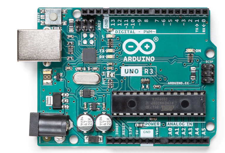
- Arduino Uno :
Arduino Uno is a microcontroller from the Arduino Family. It was developed by Arduino. Arduino Uno has 20 I/O pins, 6 are analog pins and 14 are digital pins.

For more details, pinout and datasheet, you can visit https://docs.arduino.cc/hardware/uno-rev3
- Push buttons – 5: It is a switch. it is only on condition when pressing the button.
- Ultrasonic sensor - HC-SR04: It is a device that calculates the distance between objects by emitting ultrasonic waves.
- LCD 16X2 LCD: LCD (Liquid Crystal Display) is a type of flat panel display used to print values.
Software Requirements
- Arduino Ide : Arduino IDE (Integrated development environment) is software that is used to dump the program into boards. Arduino- IDE's major use is to build electronics-related projects. Arduino is an open-source platform simple and easy-to-understand platform for coding.
HOW TO INSTALL ARDUINO IDE CLICK ON THE LINK :
https://techieyantechnologies.com/2022/10/installation-of-arduino-ide/
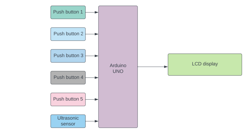
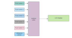
Block diagram
In the following block diagram push, buttons, and ultrasonic sensors are input devices that send data to Arduino. Lcd is an output device that receives information from the Arduino to display.
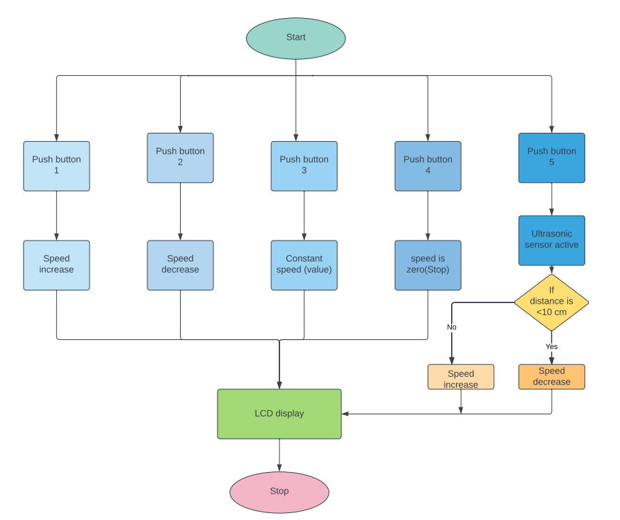
Flow Chart
A flowchart is a diagram that shows a process’s steps in proper order. Similarly, the following flowchart talks about the steps involved in the project and the sequential flow of the code also. So, as it starts, it first checks for the button pressed by the user. If button 1 is pressed then the speed of the vehicle will be increasing. if button 2 is pressed then the speed will be decreasing. button 3 is for constant speed. button 4 is to bring down the speed of the vehicle to 0. The 5-button works on an ultrasonic sensor. If anything is in front of the vehicle then the speed will be decreasing else the speed will increase. All the values will be displayed on LCD.
*website used to make Flow Chart and Block Diagram : https://www.lucidchart.com/pages/
PIN CONNECTIONS
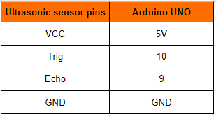
Ultrasonic sensor
The following pin connection is about the connection of ultrasonic pins with Arduino Uno. The Ultrasonic Sensor has 4 pins Vcc, Trig(Trigger), Echo & Ground. Vcc pin of ultrasonic is connected to 5V of Arduino Uno, Trig is connected to D10, Echo is connected to D9, and Ground(GND) is connected to GND
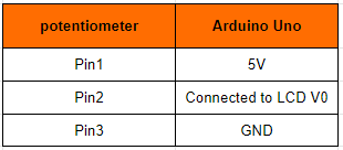
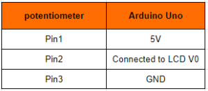
Potentiometer
The potentiometer has 3 pins GND, VCC, and output. where Pin1 is connected to the 5V of the Arduino Uno. Pin2 is Connected to LCD V0. Pin 3 is connected to the GND of the Arduino Uno.
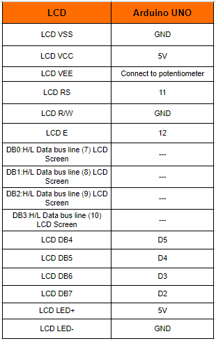
LCD
VSS is connected to the GND of the Arduino Uno.VCC is connected to the VIN of the Arduino Uno.VEE is connected to the potentiometer of the Arduino Uno.RS is connected to the 11th pin of the Arduino Uno.R/W is connected to the GND of the Arduino Uno. E is connected to the 12th pin of the Arduino Uno.DB4is connected to the A5 pin of the Arduino Uno.DB5 is connected to the A4pin of the Arduino Uno.DB6 is connected toA3 of the Arduino Uno.DB7 is connected toA2 of the Arduino Uno.LED+ve is connected to the Vin of the Arduino Uno. LED-ve is connected to the GND of the Arduino Uno.
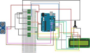
Circuit diagram
The circuit diagram to understand the connection made to different devices.
Note: Make sure to take proper precautions while connecting the components.

Working
The next step after setting up the connection is to upload code to Arduino Uno and power it. When the system is turned on, Arduino continues to watch the readings of the buttons, the button is pressed and the Arduino Uno will perform the task.
Conclusion
Here, we developed an adaptive cruise control car that is used to automate cars. Here we can avoid a lot of accidents happening around the world. Overspeed of the vehicles can be reduced.
Working Code
#include <LiquidCrystal.h>               //Using the Arduino as the controller device, the library Allows communication with liquid crystal displays (LCDs).
LiquidCrystal lcd(A0,A1,A2,A3,A4,A5);    // initialize the library by associating any needed LCD interface pin with arduino uno
int i = 0;                               //interger i is defined to store the value of buttons
int j;                                   //interger j is defined to store the value of buttons
int h;                                   //interger h is defined to store the value of buttons
int b1 = 5;                              //button1 pin connecetd to pin 5 of Arduino UNO
int b2 = 6;                              //button1 pin connecetd to pin 6 of Arduino UNO
int b3 = 4;                              //button1 pin connecetd to pin 4 of Arduino UNO
int b4 = 3;                              //button1 pin connecetd to pin 3 of Arduino UNO
int b5 = 2;                              //button1 pin connecetd to pin 2 of Arduino UNO
const int trigPin = 9;                   // attach pin 9 Arduino to pin trig of HC-SR04
const int echoPin = 10;                  // attach pin 10 Arduino to pin echo of HC-SR04
// defines variables
long duration;                           // variable for the duration of sound wave travel
int distance;                            // variable for the distance measurement
void setup() {
  pinMode( b1 , INPUT_PULLUP);           //Set button1 as INPUT device
  pinMode( b2 , INPUT_PULLUP);           //Set button2 as INPUT device
  pinMode( b3 , INPUT_PULLUP);           //Set button3 as INPUT device
  pinMode( b4 , INPUT_PULLUP);           //Set button4 as INPUT device
  pinMode( b5 , INPUT_PULLUP);           //Set button5 as INPUT device
  pinMode(trigPin,OUTPUT);               // Sets the trigPin as an OUTPUT
  pinMode(echoPin,INPUT);                // Sets the echoPin as an INPUT
  lcd.begin(16,2);                       // set up the LCD's number of columns and rows:
  lcd.setCursor(0,0);                    // to display the values on to the top left of LCD
  lcd.print("Speed:");                   // print the value on LCD
}
void loop() {
int v1 = digitalRead(b1);               //Reads the value from a button1 and store the value in V1
int v2 = digitalRead(b2);               //Reads the value from a button2 and store the value in V1
int v3 = digitalRead(b3);               //Reads the value from a button3 and store the value in V1
int v4 = digitalRead(b4);               //Reads the value from a button4 and store the value in V1
int v5 = digitalRead(b5);               //Reads the value from a button5 and store the value in V1
if (( v1 == LOW)&&(v2 == HIGH)&&(v3== HIGH)&&(v4==HIGH)&&(v5 == HIGH))
{
   j = (i += (1 - (i >= 150)));          //incrementing the i value
  lcd.setCursor(0,0);
  lcd.print("Speed:");
  lcd.setCursor(0,1);
  delay(500);
  lcd.println(i);
};
if((v1 == HIGH)&&(v2 == LOW)&&(v3 == HIGH)&&(v4==HIGH)&&(v5 == HIGH)){
  i--;                                  // decremenying the value of i
  lcd.setCursor(0,0);
  lcd.print("Speed:");
  delay(500);
  lcd.setCursor(0,1);
  lcd.print(i);
 }
 if ((v1 == HIGH)&&(v2 == HIGH)&&(v3== LOW)&&(v4==HIGH)&&(v5 == HIGH)){
  lcd.setCursor(0,0);
  lcd.print("Speed:");
  lcd.setCursor(0,1);
  delay(500);
  lcd.print(i);
  delay(1000);
  lcd.clear();
  lcd.setCursor(0,0);
  lcd.print("Speed");
  delay(500);
 }
 if ((v1 == HIGH)&&(v2 == HIGH)&&(v3==HIGH)&&(v4==LOW)&&(v5 == HIGH)){
   lcd.setCursor(0,0);
   lcd.print("Speed:");
   lcd.setCursor(0,1);
   delay(1000);
   lcd.println(0);
  }
 if ((v1 == HIGH)&&(v2 == HIGH)&&(v3==HIGH)&&(v4== HIGH)&&(v5 == LOW)){
  digitalWrite(trigPin, LOW);                    // Clears the trigPin condition
  delayMicroseconds(2);
  digitalWrite(trigPin, HIGH);                   // Sets the trigPin HIGH (ACTIVE) for 10 microseconds
  delayMicroseconds(10);
  digitalWrite(trigPin, LOW);                    // Reads the echoPin, returns the sound wave travel time in microseconds
  duration = pulseIn(echoPin, HIGH);             //calculating time
  distance= duration*0.034/2;                    // calculating distance
  if(distance >20){                               // applying condition
    i--;
    delay(1000);
    lcd.setCursor(0,0);
    lcd.print("Speed:");
    lcd.setCursor(0,1);
    lcd.print(i);
  }
 }
}
Click here to download the code for adaptive cruise control of the car
If You Face Any Issue Feel Free To Contact us Any Time.


Need the source code or help?
Contact us for model weights, datasets, or guidance on running this project.