
A Smart weather Forecasting System
Abstract
Smart technology called Weather Forecasting System is utilized to obtain real-time reporting of weather conditions. Current weather analysis could be used to anticipate the state of the atmosphere in the future. Weather forecasts are often created using large, complex physics models that take into consideration a wide range of atmospheric conditions over a long period of time. The weather system’s disturbances frequently make these situations unstable. The purpose of this project is to illustrate a clever forecasting system that makes use of data saved in the cloud that was acquired using sensors to anticipate the necessary parameters over the internet and to project the predictable trend.Here, we are using a barometric sensor, DHT11 sensor, and raindrop sensor to measure the climatic conditions. if any sensor reads the values. the values will be displayed on the LCD and give an alert via a buzzer sound. The main advantage of using this smart weather forecasting system saves time. so we are able to predict and prepare for future climatic conditions.
Introduction
The weather is constantly and quickly changing all throughout the world. In today’s world, accurate forecasts are crucial. We depend significantly on weather forecasts for everything from agriculture to business, transport, and daily commuting. It is crucial to accurately predict the weather in order to maintain simple and seamless mobility as well as safe day-to-day operations because the entire planet is experiencing the effects of ongoing climate change. Every person’s life is heavily influenced by weather observation. Numerous obstacles are created in a variety of sectors as a result of the impact on the environment. including things like building, industry, and agriculture diverse fields But the measured impact primarily occurs in industries and agriculture. Agriculture, as we all know plays a significant part in the Indian economy. Smart agriculture has been a topic of discussion in recent months. Weather forecasting provides prior information about the weather to organizations and people to get the time and measures for minimizing the losses that can be incurred. It has become a necessity for the tourism and agriculture sectors. There are various sensors used in a project to detect the weather
Components Required
Hardware Requirements
- Arduino Uno : Arduino Uno is a microcontroller from the Arduino Family. It was developed by Arduino. cc and is based on the Microchip ATmega328P microcontroller. Uno has 20 I/O pins, 6 are analog pins and 14 are digital pins.
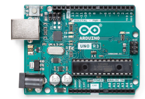
For more details, pinout and datasheet, you can visit : https://docs.arduino.cc/hardware/uno-rev3
- Humidity sensor: it is an electronic device that measures the water vapor present in the air.
- Barometric pressure sensor: it is a type of sensor that detects atmospheric pressure.
- Raindrop sensor: it detects the rain.
- LCD display: LCD (Liquid Crystal Display) is a type of flat panel display used to print values.
Software Requirements
Arduino IDE: Arduino IDE (Integrated development environment) is software used to dump the program into boards. Arduino- IDE’s major use is to build electronics-related projects. Arduino is an open-source platform simple and easy-to-understand platform for coding.
HOW TO INSTALL ARDUINO IDE CLICK ON THE LINK :
https://techieyantechnologies.com/2022/10/installation-of-arduino-ide/
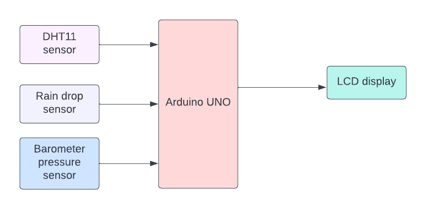
Block diagram
In the following block diagram for smart weather forecasting system project DHT11 sensor, raindrop sensor, and barometer pressure sensor are the input devices. LCD and buzzer are the output devices. Arduino Uno is the microcontroller.
Flow Chart
First the values of the barometric sensor, DHT11 sensor, and raindrop sensor are read. if the values are being read then the buzzer will be activated, else the buzzer will not get activated.
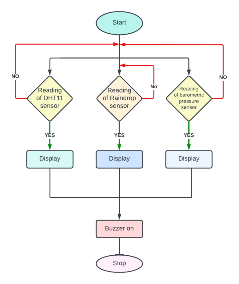
*website used to make Flow Chart and Block Diagram : https://www.lucidchart.com/pages/
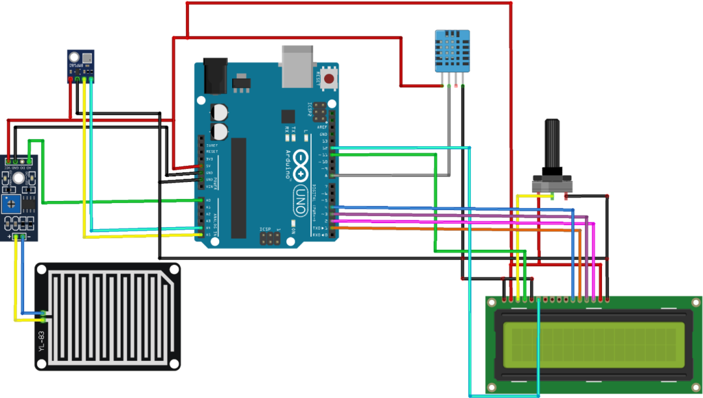
Pin Wiring
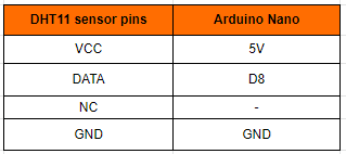
DHT11 Sensor
The VCC pin of the DHT11 sensor is connected to the 5v pin of the Arduino. The data pin of the DHT11 sensor is connected to the D8 pin of the Arduino. The NC pin of the DHT11 sensor is not connected to any pin of the Arduino. The GND pin of the DHT11 sensor is connected to the GND pin of the Arduino.
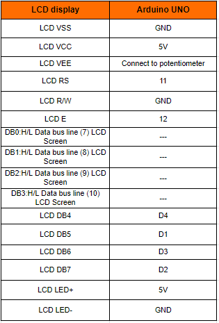
LCD
The LCD display has 16 pins. VSS is connected to the GND of the Arduino Uno.VCC is connected to the 5v of the Arduino Uno.VEE is connected to the potentiometer of the Arduino Uno.RS is connected to the 11th pin of the Arduino Uno.R/W is connected to the GND of the Arduino Uno. E is connected to the 12th pin of the Arduino Uno.DB4is connected to the 4th pin of the Arduino Uno. DB5 is connected to the 1st pin of the Arduino Uno. DB6 is connected to the 3rd pin of the Arduino Uno. DB7 is connected to the 2nd pin of the Arduino Uno. LED+ve is connected to 5v of the Arduino Uno. LED-ve has connected to GND of the Arduino Uno
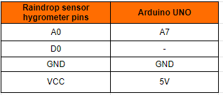
Hygrometer Sensor
The VCC pin of the Raindrop hygrometer sensor is connected to the 5v pin of the Arduino. The A0 pin of the Soil hygrometer sensor is connected to the A7 pin of the Arduino. The D0 pin of the Soil hygrometer sensor is not connected to any pin of the Arduino. The GND pin of the Soil hygrometer sensor is connected to the GND pin of the Arduino.
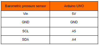
Barometer Pressure Sensor
The Vin pin of the DHT11 sensor is connected to the 5v pin of the Arduino. The SCL pin of the DHT11 sensor is connected to the A5 pin of the Arduino. The SDA pin of the DHT11 sensor is connected to the A4 pin of the Arduino. The GND pin of the DHT11 sensor is connected to the GND pin of the Arduino.
Circuit diagram
Note: make sure to take proper precautions while connecting the components.
Working
Barometric sensor, DHT11 sensor, and raindrop sensor read the values. The values which are read by the sensors are shown in the LCD display. if the values are detected the buzzer will be activated and gives an alert. else the buzzer will not be in condition.
Conclusion
Hence, the weather forecasting system has been successfully built. We can come to the conclusion that the IoT-based weather rating system is highly effective and efficient, as the gathered data can also be sent to the cloud.
Working Code
#include <Adafruit_BMP085.h>
#include <Wire.h>                                   // include the library code:
#include <LiquidCrystal.h>
LiquidCrystal lcd(13, 12, 11, 10, 9, 8);//RS,EN,D4,D5,D6,D7

char PRESSURESHOW[4];                               // initializing a character of size 4 for showing the result
char TEMPARATURESHOW[4];                            // initializing a character of size 4 for showing the temparature result
Adafruit_BMP085 bmp;
#include "DHT.h"                                   // set the DHT Pin
#define DHTPIN 8                                   // initialize the library with the numbers of the interface pin
#define DHTTYPE DHT11
DHT dht(DHTPIN, DHTTYPE);                         //defining the pin and the type of dht sensor is used
int rainAnalogPin = A0;                           // rain sensor is connected to pin A0 of arduino uno
int rainDigitalPin = 2;                           // rain sensor is connected to pin A0 of arduino uno

void setup() {
  pinMode(rainAnalogPin, INPUT);                  //set rain sensor as the input device
  pinMode(rainDigitalPin, INPUT);                 //set rain sensor as the input device

  // set up the LCD's number of columns and rows:
  lcd.begin(16, 2);
  dht.begin();                                   // Print a message to the LCD.
  lcd.print("Temp:  Humidity:");
  delay (3000);
  lcd.print(" BMP180 Sensor");
  lcd.setCursor(0, 1);
  lcd.print("Temp. & Pressure");
  lcd.setCursor(0, 2);
  delay (3000);

lcd.clear();                                       //clear display
Serial.begin(9600);
 if (!bmp.begin())
{
Serial.println("ERROR");                            //if there is an error in communication
while (1) {}
}
}
void BW180()
{

lcd.print("Pressure= ");                              // print name
String PRESSUREVALUE = String(bmp.readPressure());

// convert the reading to a char array
PRESSUREVALUE.toCharArray(PRESSURESHOW, 4);
lcd.print(PRESSURESHOW);
lcd.print("hPa ");
lcd.setCursor(0, 1);
lcd.print("Temparature=");                          // print name

String TEMPARATUREVALUE = String(bmp.readTemperature());

// convert the reading to a char array
TEMPARATUREVALUE.toCharArray(TEMPARATURESHOW, 4);
lcd.print(TEMPARATURESHOW);
lcd.print("C ");
lcd.setCursor(0, 0);                            //set the cursor to column 0, line1
delay(500);
}
void Humidity() {
  delay(500);

  // set the cursor to column 0, line 1
  // (note: line 1 is the second row, since counting begins with 0):

  lcd.setCursor(0, 1);

  // read humidity
  float h = dht.readHumidity();

  //read temperature in Fahrenheit
  float f = dht.readTemperature(true);

  if (isnan(h) || isnan(f)) {
    lcd.print("ERROR");
    return;
  }

  lcd.print(f);
  lcd.setCursor(7,1);
  lcd.print(h);
}
void rainsensor () {

  // read the input on analog pin 0:
  int sensorAnalogValue = analogRead(rainAnalogPin);
  Serial.print("Rain sensor analog value: ");
  Serial.println(sensorAnalogValue);

  // read the input on digital pin 2:
  int sensorDigitalValue = digitalRead(rainDigitalPin);
  Serial.print("Rain sensor digital value: ");
  Serial.println(sensorDigitalValue);

//digital output
 if(sensorDigitalValue == HIGH)                  //High means rain detected; In some case vise versa
 {
 Serial.println("Rain Detected");
 }
 else {
 Serial.println("No Rain Detected");
 }
 delay(250);
}

void loop(){
  }
If You Face Any Issue Feel Free To Contact us Any Time.