Fuzzy Control DC Motor
Abstract
Dc motor have a wide range of applications in the real world, and speed control of direct control(DC) motors is essential in practical applications. Mostly dc motors are utilized in industries, elevators, etc. Speed control of the DC motor enables us to operate the dc motor at our desired speed according to our application. The main motto of the project is to develop an efficient, effective and reliable way of speed control of the dc motor. PID controller has its own advantages and disadvantages, to overcome the drawbacks of the PID controller Fuzzy logic will be implemented in the speed control of the DC motor for better results and fewer in controlling. A fuzzy logic controller is a design based on the membership function and rule base. FLC(Fuzzy logic controller) products are introduced to get faster step response than PID controllers. A fuzzy logic controller is implemented and developed in the MATLAB-Simulink environment. The setting time(Ts), rise time(Tr), peak time(Tp) and percent overshoot are the factors by which controllers’ performance is analyzed. Finally, this project enables the user to utilize the fuzzy logic controller in speed control of the dc motor according to the application.

Code Description & Execution
Algorithm Description
The above figure illustrates the block diagram of a fuzzy-controlled DC motor. Reference speed (Desired speed) is input for the fuzzy logic controller, and FLC(Fuzzy logic controller) gives input to the DC motor according to the given reference speed. The DC motor converts the electrical input to mechanical output in RPM (revolutions per min). FLC has a feedback system similar to the PID controller. The actual speed of the motor is given to FLC through feedback in RPM, FLC calculates the difference in the desired speed and actual speed and makes changes in input given to the DC motor according to the output of the motor. Manual calculations should be done in the FLC according to our application for better and best control of the DC motor.

Block diagram – Fuzzy logic control of DC motor.
Model Description
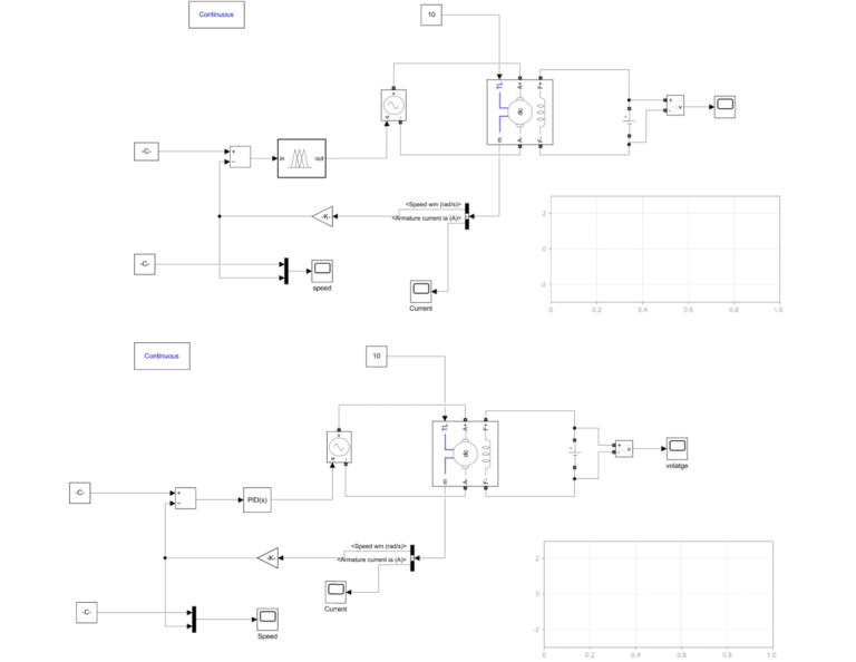
The simulation of fuzzy logic control of the DC motor is illustrated in the above figure. Reference speed and actual speed of the motor are the inputs given to FLC by a constant block and feedback loop. The DC motor block replicates the real time Dc motor in the simulation. Dc voltage input to the motor is given by the DC voltage source block in Simulink. The output waveform of DC motor speed by both PID controller and FLC are viewed in the scope block.
Steps to Execute the Code
- Download the zip file and unzip it
- Open MATLAB and click on Simulink icon on home tab
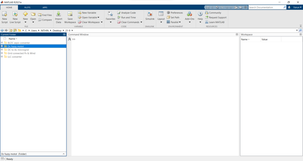
3. Click on open when the following window pops up.
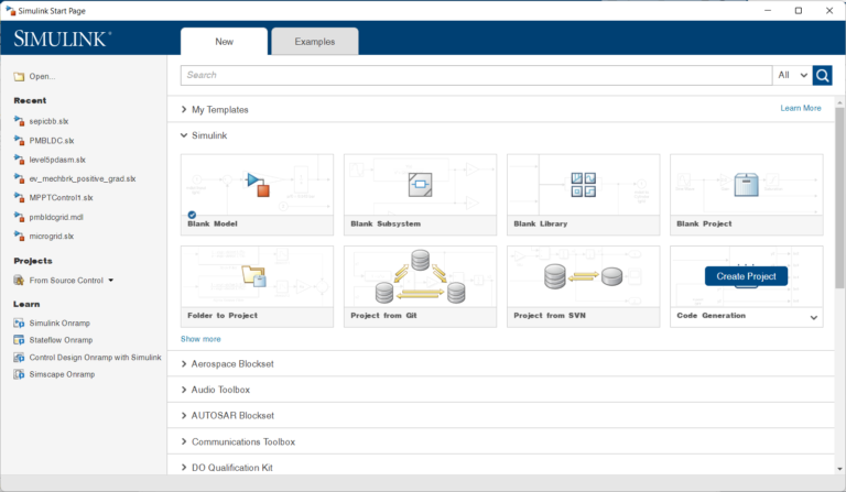
4. A window pops up from which select the required file and click on open.
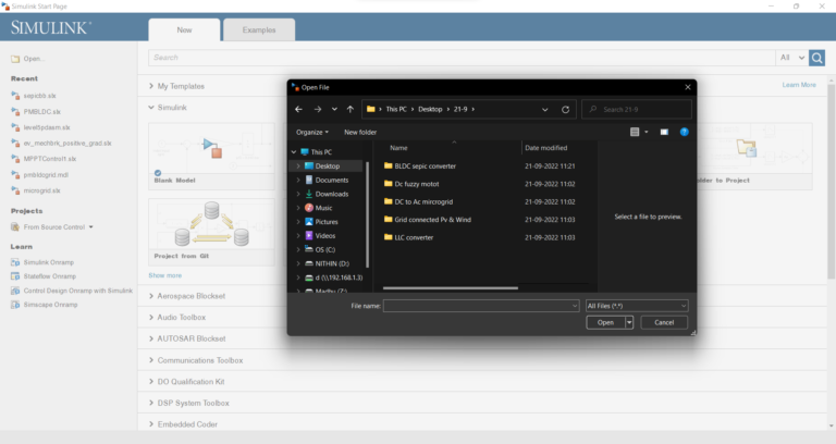
5. After opening the file we need to make some progress.
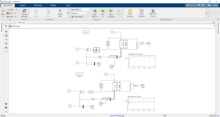
6. We need to run this ‘fuzzy untitled.fis’ before going into the simulation.
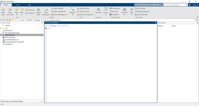
7. After running the ‘fuzzy untitled.fis’. Fuzzy logic interfaces will pop up.

8. We need to export the file to workspace before running the Simulink file.
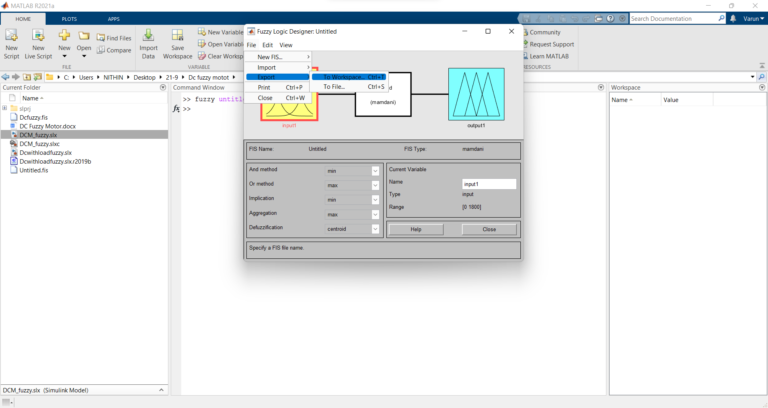
9. Click on run which is in the simulate tab. Once the simulation is ready click on scope to view the results.
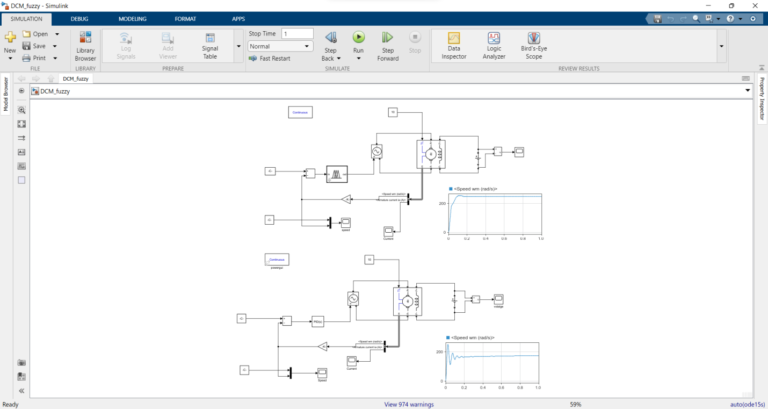
Result
It shows the speed of the dc motor.
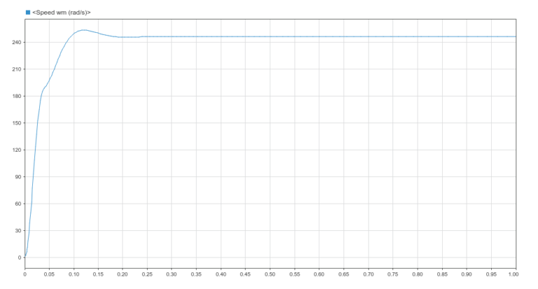
It shows the speed of the PID controller.
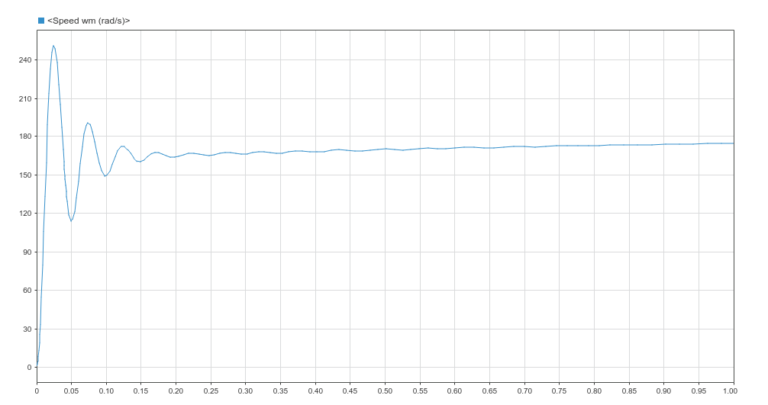
Issues Faced
- Because of the version difference, functions might have changed and errors might occur so change functions according to the version(this simulation was done on R2022a).
