ARDUINO BASED FINGERPRINT DOOR LOCKING SYSTEM
Abstract
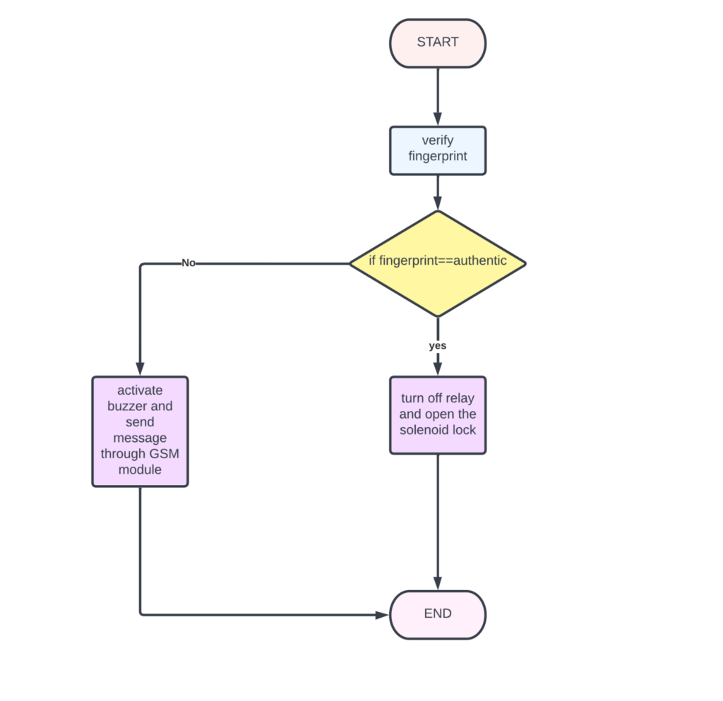
The main objective of this project is to provide a sense of safety and security by making a door locking system based on fingerprint authentication. In this system a simple arduino nano is used as a microcontroller which is interfaced with fingerprint sensor, relay, solenoid lock and LCD. When the user keeps the finger on the fingerprint sensor, it will verify whether the fingerprint is authentic or not. If the fingerprint is authentic then the door lock will be opened with the help of relay and a message will be popping on LCD stating “fingerprint verified welcome back home”. If the fingerprint is not authentic, then the buzzer will get activated and a message will be displayed stating “unauthorised fingerprint”. This system is very useful for security purposes. In the existing system, there was a traditional approach to locking the door, and in further advancements, there was a pattern-based door locking system, but in the proposed system there is no traditional approach, and from this one can feel safe and secure as the probability of theft is reduced.
Introduction
Security and protection systems are designed to protect and guard assets. This system can be used in a variety of settings, including homes, offices, colleges, and industries, to allow a person into a room fingerprint sensor using fingerprints as biometric authentication. In this modern era, fingerprint authentication has become common as there are many applications such as: in mobile phones (for security purposes), in colleges(for biometric attendance), in offices(to track employees’ login and logout timings), in lockers(to safeguard important files, jewellery etc). Compared to patterns and passwords, which can be cracked with little effort, fingerprint-based locks are tough to crack as everyone has a unique fingerprint. Even so, one cannot match his/her finger’s fingerprint with another finger.
Components Needed
- Arduino uno
- Relay
- Solenoid lock
- Buzzer
- LCD
- Fingerprint sensor
- LED
- GSM module
Flow Chart

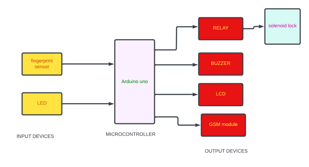
Block Diagram
In the following block diagram fingerprint sensor and LED are the input devices. Relay, solenoid lock, GSM module, LCD and buzzer are the output devices. Arduino uno is the microcontroller.

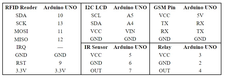
Pin Connection

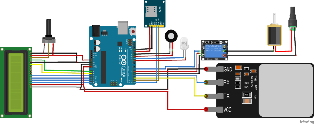
Circuit Diagram

