Enhanced Energy Management Strategy for an Electric Vehicle Fast Charging DC Microgrid
Abstract
This abstract presents an enhanced energy management strategy for DC microgrids with electric vehicle fast charging (EVFC) capabilities. This strategy mainly focuses on developing energy utilization, minimizing operational costs, and effectively integrating EV charging within the microgrid and renewable energy sources. The microgrid is a storage system containing wind turbines, solar panels, loads, and generators. By managing the charging and discharging operations, the strategy checks a harmonious balance between energy supply and demand. This approach increases the utilization of renewable energy sources and reduces dependence on external power sources. The enhanced energy management strategy uses a graded control structure to improve or enhanced energy management strategy with three layers. Moreover, a customized fast charging algorithm is implemented to optimize the charging process for EVs while maintaining microgrid performance and stability. The simulation results show crucial improvements in energy utilization, load balancing, and operational costs. This makes the proposed strategy an accurate solution for efficient energy management in DC microgrids with fast EV charging.
Code Description & Execution of Enhanced Energy Management Strategy for an Electric Vehicle Fast Charging DC Microgrid
Algorithm Description
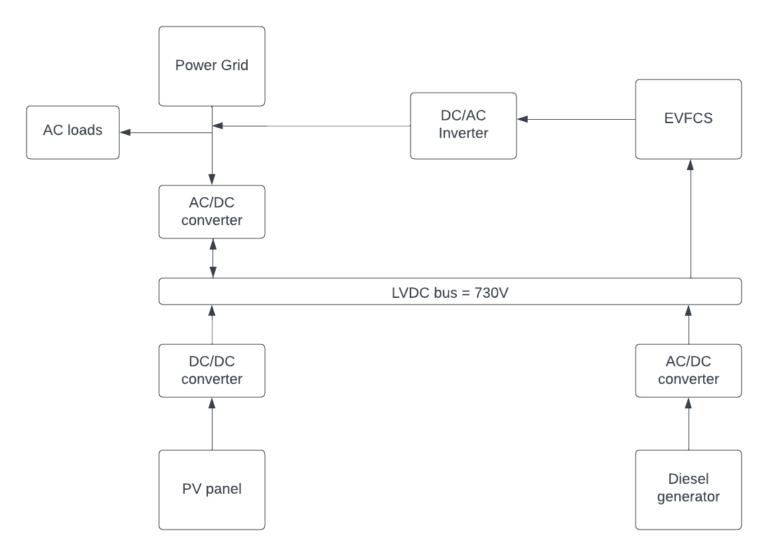
Fig 1: Proposed System
The proposed system visually represents the enhanced energy management strategy’s components arrangement and interconnections in a DC microgrid with electric vehicle fast charging (EVFC). It provides a clear system layout and architecture so that it contains more sensible elements.
The inverter control system controls the operation and performance of inverters within the microgrid. It regulates power flow, voltage levels, and frequency to ensure efficient conversion and distribution of electricity.
The constant current battery charger control system manages the charging process of batteries in the microgrid. It maintains a controlled and stable current during charging, preventing overcharging or undercharging, and securing the efficiency and duration of the battery storage system.
Code Description:
The Simulink file is a .slx file that represents the Simulink model. It contains blocks of components and devices.
Steps to Execute the Code
Download the zip file and unzip it
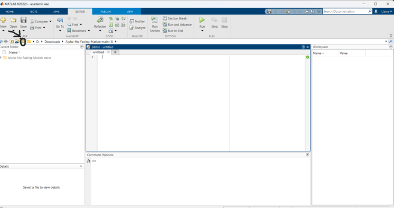
Open Matlab and click on the ‘browse for folder’ icon as shown below.
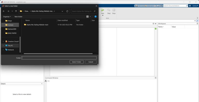
3. A pop-up window appears from which we can select the folder
4. Double-click the .slx file in the current folder
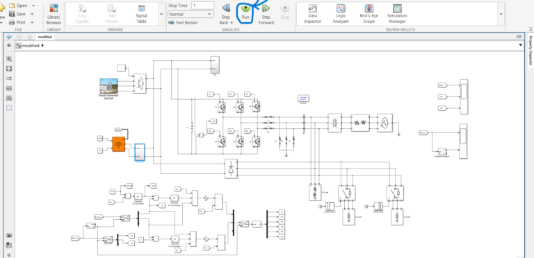
5. Run the Simulink model as shown below
Results of Enhanced Energy Management Strategy for an Electric Vehicle Fast Charging DC Microgrid
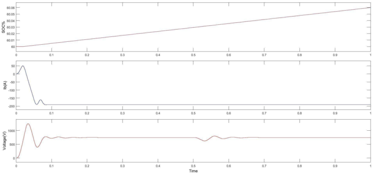
Fig 2: Charging operation SOC, Battery current Ib, Voltage
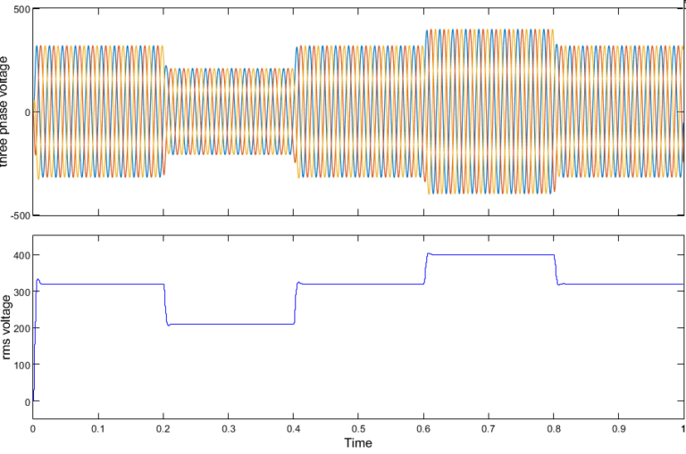
Fig 3: Three-phase voltage profile and Voltage profile at load point
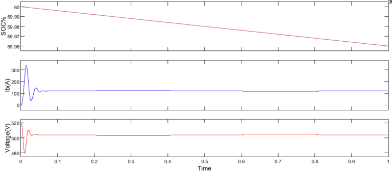
Fig 4: Discharging operation SOC, Battery current Ib, Voltage
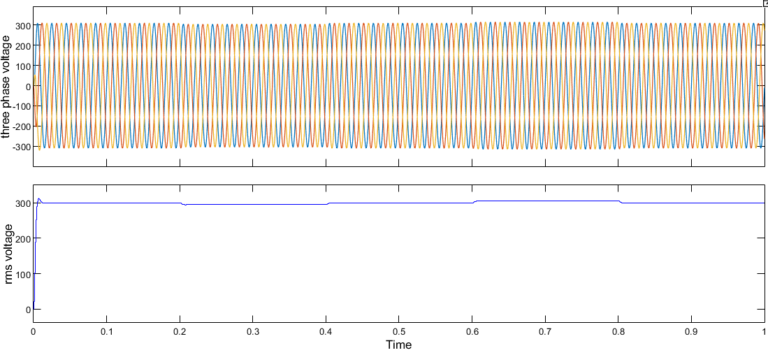
Fig 5: Three-phase voltage profile and Voltage profile at load point with D-STATCOM.
Issues Faced
All the necessary toolboxes required for the project file to Run should be installed in Matlab. If not errors can occur in the diagnostics box.
Connections to the blocks should be properly done.
Parameter values to the Simulink blocks should be given correctly.