
Overview
MEASURED GIGANTIC MU MIMO OFDM UP LINK
Abstract
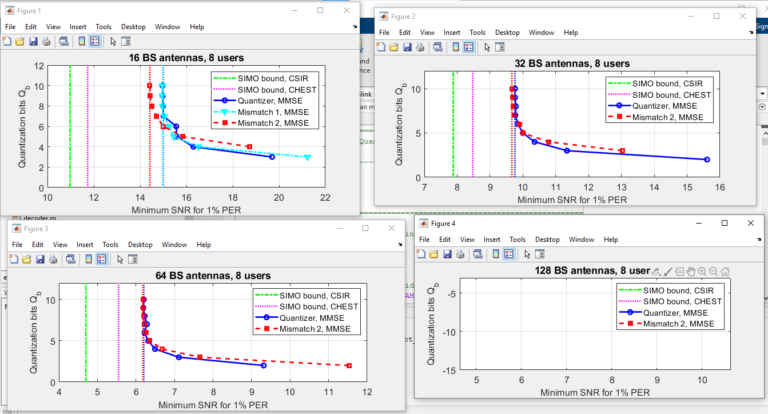
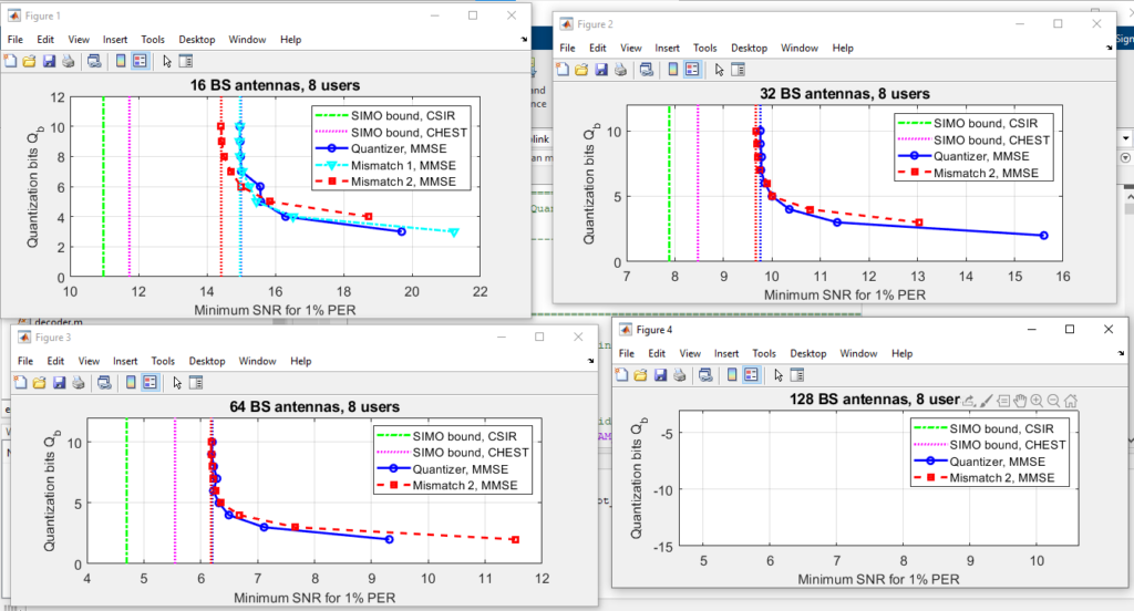
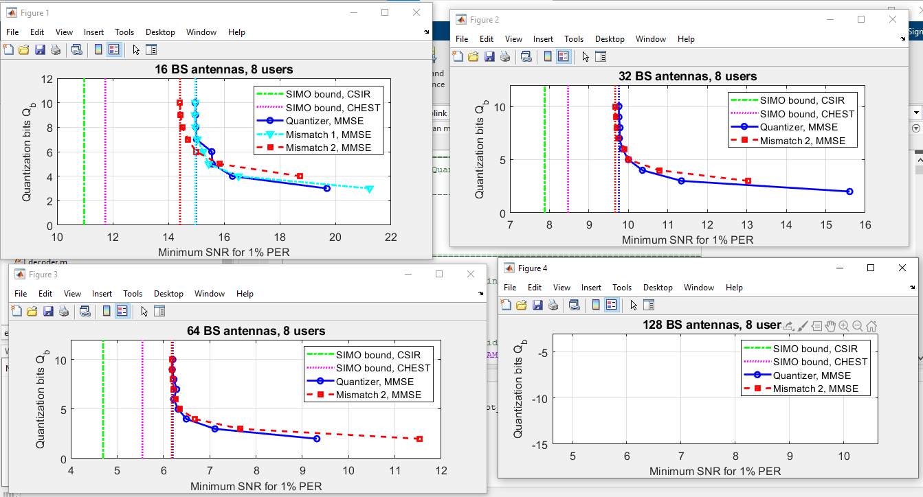
Wireless communication systems are utilized everywhere in this digital era. Wi-fi, Mobile Communication Systems, Microwave Communication, Broadcast Radio are examples of wireless communication systems where “Multiple users (MU)-multiple inputs and multiple outputs (MIMO)” is implemented in these systems. Orthogonal frequency division multiplexing (OFDM) enhances the performance of the wireless systems by providing wide bandwidth which allows them to pass multiple signals at different frequencies. Mu-MIMO OFDM wireless systems provide significant power, cost savings and Significantly reduces the raw analog-to-digital converter (ADC) data that needs to be sent from the spatially separated antenna array to the baseband processing unit. . In this project we look in to uplink performance of a measured gigantic MU-MIMO system that deploys orthogonal frequency-division multiplexing (OFDM) for wideband communication. Our results demonstrate the performance of the MU-MIMO systems in terms of the ratio between measured bits and signal to noise ratio(SNR) for different numbers of bits and multiple antenna.
Code Description & Execution
Algorithm Description
 overview of MU - MIMO - OFDM uplink system
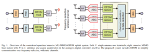
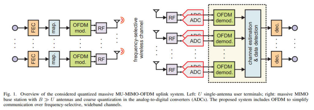
The above figure describe model structure of MU-MIMO (Multiple user- multiple input and multiple output) system. We assume a coded MU-MIMO uplink system that employs spatial multiplexing. It consists of U independent single-antenna users 6 communicating with a BS with B ≥ U receive antennas. Consider a frame-based OFDM transmission, where each OFDM symbol consists of frequencies. We continue to assume that communication takes place in two phases
overview of MU - MIMO - OFDM uplink system
The above figure describe model structure of MU-MIMO (Multiple user- multiple input and multiple output) system. We assume a coded MU-MIMO uplink system that employs spatial multiplexing. It consists of U independent single-antenna users 6 communicating with a BS with B ≥ U receive antennas. Consider a frame-based OFDM transmission, where each OFDM symbol consists of frequencies. We continue to assume that communication takes place in two phases
- Training phase U consists of OFDM symbol
- D data transmission phase consisting of OFDM symbol
Code Description
Allpath.m: Allpath.m file add required files (inputs, outputs and mains file ) to the path Err_plot.m: To plot the all outputs at different number of bits and multiple antenna, which is located in the results folder in the given zip file Note:- To known the more details about the codes and functions in the file open the files in matlab and read the tags (%) in the code for better understanding
- Matlab file or codes are saved in .m and .mat format
Steps to Execute the Code
- Download the zip file of this project and unzip it.
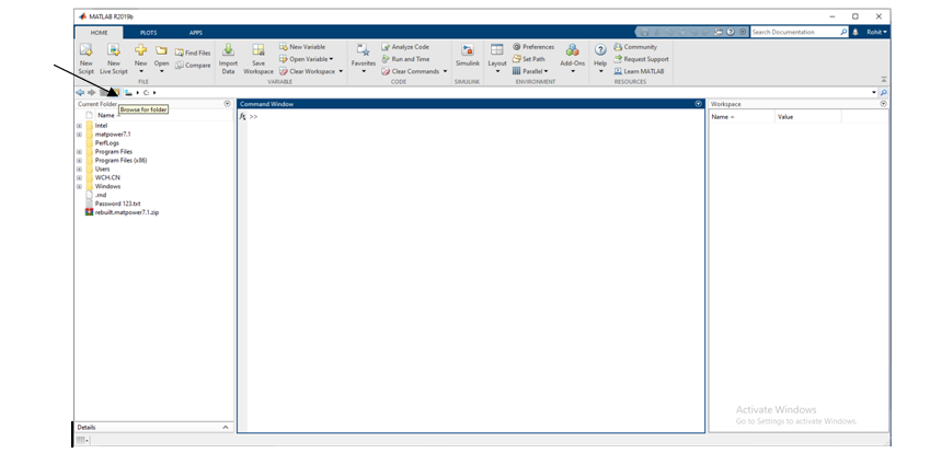
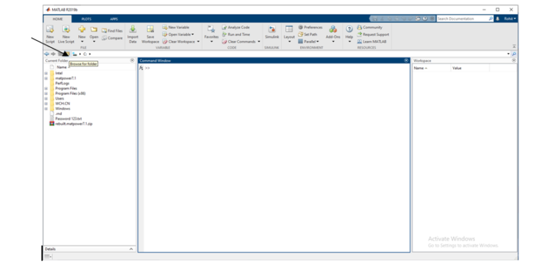
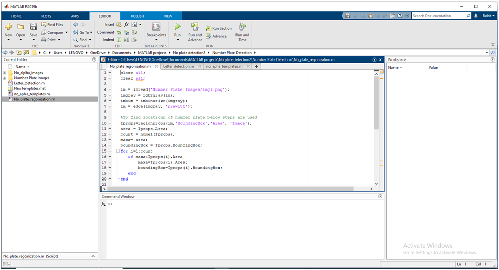
- Open matlab and click on the ‘browse for folder’ icon as shown below
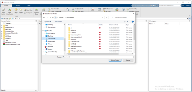
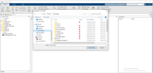
- A pop up window appears from which we can select the folder.
- Run “allpath.m”file to add required functions, inputs and outputs
- Go to plots folder in the given file you will find “err_plot.m” file, run the file you will get the required output.
 5. Click on Editor (present at top), Run the No_plate-regonization.m by clicking on Run button , code will be executed and output will be displayed.
Result
Issues Faced
- “Not enough input arguments” error occurs when you run the function files, which are not main codes these functions are utilized in main code.
- The formulas and algorithm are implemented in the function, to understand formulas implemented read the tags in the function files.
Reference:


Need the source code or help?
Contact us for model weights, datasets, or guidance on running this project.