
← Education

Integrated Wind-Solar Cogeneration with Grid Connection Using Back-to-Back Voltage Source Converters

Overview
Integrated Wind-Solar Cogeneration with Grid Connection Using Back-to-Back Voltage Source Converters
Abstract
A hybrid system is designed to encompass a wind turbine (with a permanent magnet synchronous generator) and a solar generator. A grid is connected to the system through a back-to-back voltage source rectifier and inverter. A dc link capacitor is connected to connect the solar generator to the system. Both wind and solar power generators possess independent maximum power point tracking (MPPT) for maximizing the power from renewable energy sources. Small signal models are developed to provide firmness to the whole system. The regulation of voltage source converters is done through vector control. IGBTs in parallel with a diode are used in voltage source converters. The complete model entities are built in MATLAB/Simulink.
Code Description & Execution of Integrated Wind-Solar Cogeneration with Grid Connection Using Back-to-Back Voltage Source Converters
Algorithm Description
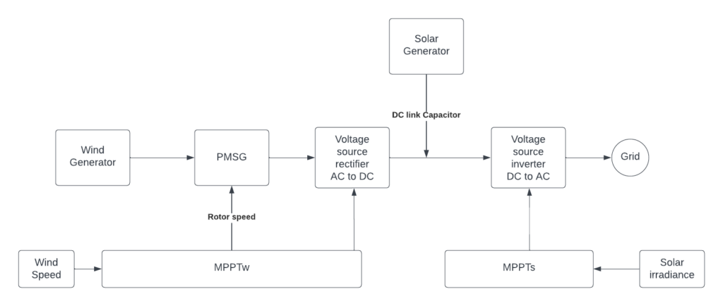
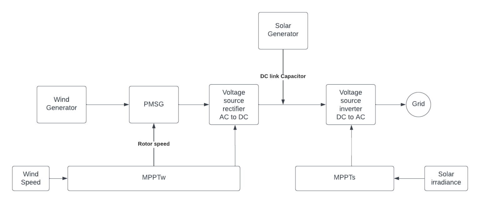
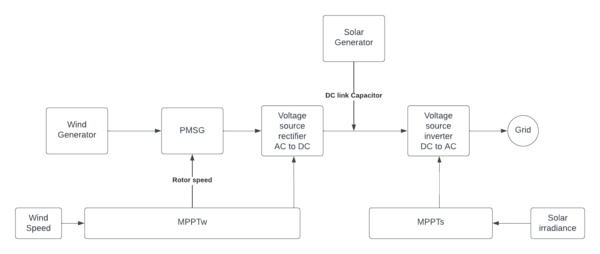
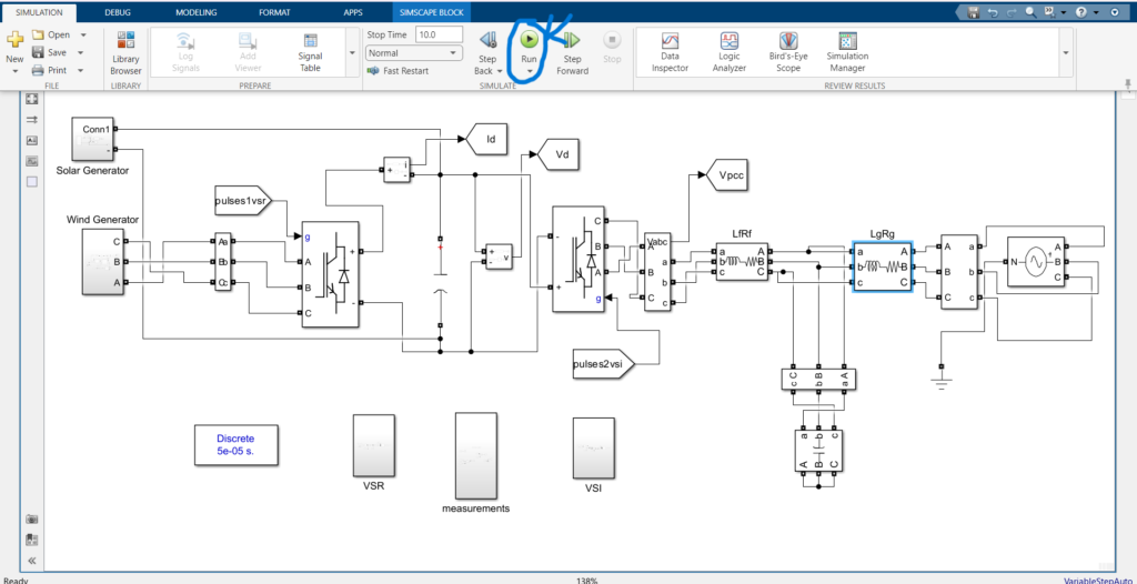
Block diagram of the hybrid system connected to a grid
A Voltage source-based rectifier VSR and a Voltage source-based inverter VSI are employed in the system for power generation. Maximum wind power is generated if the rotor speed is optimally regulated to follow changes in speed. The MPPTW for the wind generator can be used on the VSR side for this purpose. MPPTW utilizes the wind speed and generates reference values of the rotor speed. The Voltage source inverter VSI regulates the dc-link voltage and extracts the maximum solar power. There is an optimal point at the solar irradiance level, at which solar power is maximized. The MPPT of the photovoltaic generator MPPTS is responsible for evaluating the dc-link voltage and utilizes solar irradiance. The VSI transfers total DC power into the grid.
Model Description of Integrated Wind-Solar Cogeneration with Grid Connection Using Back-to-Back Voltage Source Converters
The Simulink file is a .slx file that represents the Simulink model. It contains blocks of components and devices.Steps to Execute the Code
- Download the zip file of this project and unzip it.
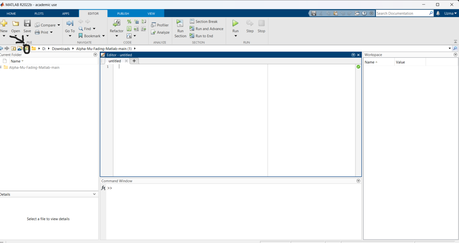
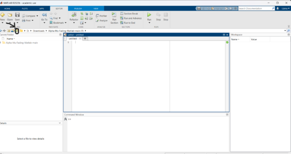
- Open Matlab and click on the ‘browse for folder’ icon as shown below.
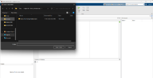
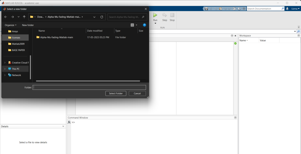
 3. A pop-up window appears from which we can select the folder
 4. Double-click the .slx file in the current folder
 5. Run the Simulink model as shown below

Results :
 Fig 1: DC voltage
 Fig 2: Grid Current
 Fig 3: PCC voltage per unit
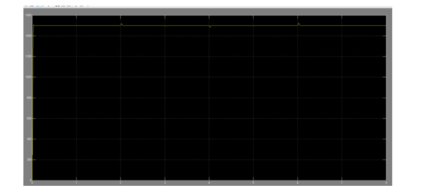
 Fig 4: PSWM speed
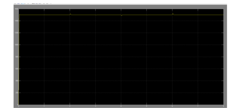
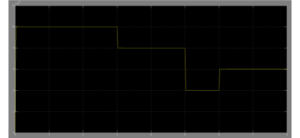
 Fig 5: PV power
 Fig 6: Solar IR
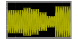
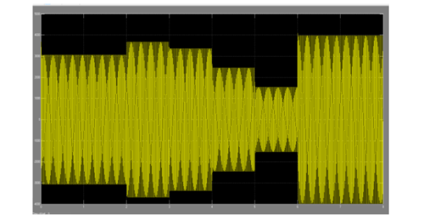
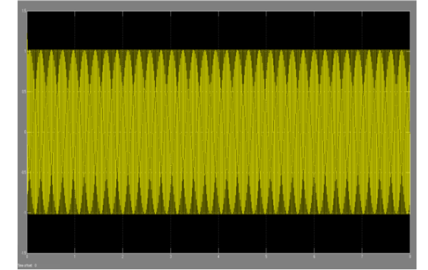
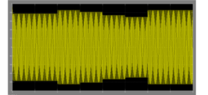
 Fig 7: VSI modulation
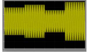
 Fig 8: VSR modulation
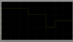
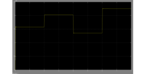
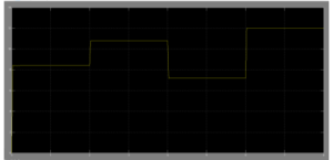
 Fig 9: Wind power
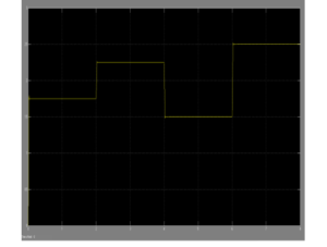
 Fig 10: Wind speed
Issues Faced
- All the necessary toolboxes required for the project file to Run should be installed in Matlab. If not errors can occur in the diagnostics box.
- Connections to the blocks should be properly done.
- Parameter values to the Simulink blocks should be given correctly.
Reference:
https://www.researchgate.net/publication/330149024_Grid-Connected_Wind-Solar_Cogeneration_Using_Back-to-Back_Voltage_Source_ConvertersContact details:
All the required data has been provided over here. Please feel free to contact me for model weights and if you face any issues.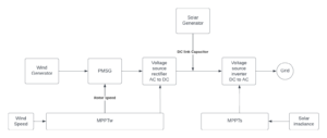








Need the source code or help?
Contact us for model weights, datasets, or guidance on running this project.