SOLAR AND FUEL CELL INTEGRATED DC TO AC MICRO GRID
Abstract
Renewable energy is emerging due to high power requirements in the world, corresponding to the increase in the power requirements implementation of microgrids should increase. Microgrids play an important role in supplying power to the consumers mainly domestic loads(light loads). The proposed microgrid consistsof a PV(Photovoltaic ) array integrated with a fuel cell. Solar powered PVarrays act as primary supply to microgrids and during low sunlight conditions or off light conditions fuel cells act as backup source to the microgrid. A lithium-ion battery is incorporated into the microgrid for storing energy generated from PV arrays. By separately addressing the steady-state and transient control problems, the control design for the DG inverters uses a new model predictive control technique that provides faster calculation time for large power systems. The proposed microgrid’s operating capabilities are demonstrated through a variety of test scenarios, and the design idea is verified. The results are then reviewed.
Code Description & Execution
Algorithm Description
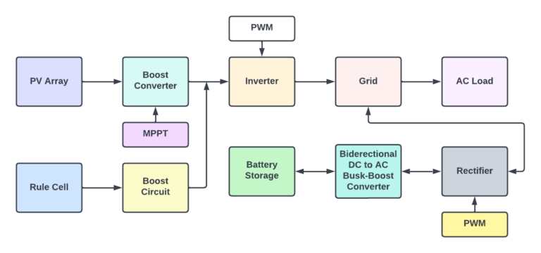
The output of Pv(Photovoltaic) array is given to the DC to DC boost circuit to improve the stability of the generated DC power from solar. P and O algorithm based maximum power point tracking technique (MPPT) to extract maximum power from PVarray. Pv array is parallel connected to the Fuel cell with a boost circuit which acts as secondary power supply. Pv array and fuel cell generated power is given to the inverter ,inverter converts DC power to AC power output of inverter is connected to the AC grid. Ac load is connected to the grid and a battery storage system is connected to AC grid through a converter and a bidirectional DC to AC buck boost converter, Pulse width modulation technique is utilized for converting AC to DC.
Block Diagram of solar and Fuel cell integrated DC to AC
Model Description
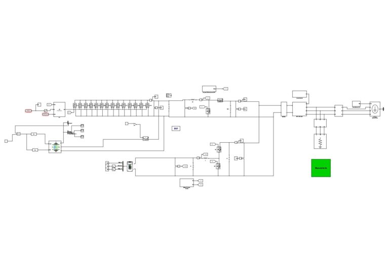
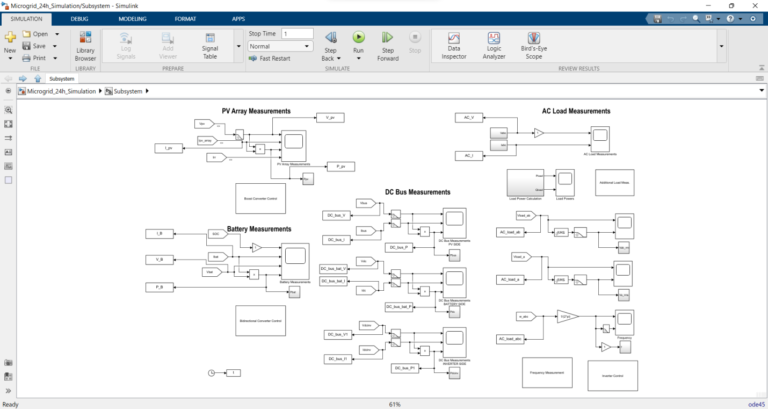
The below figure shows a simulation circuit of solar and fuel cell integrated DC to AC microgrid. Simulation circuit replicates real time circuit implementation of the project. Solar pv array block in simulation indicates the actual solar panel, different types and rating of the panels are available in the Simulink solar pv block ,according to our requirement we need to choose the type of the solar pv block. Fuel block indicates the actual replication of the fuel cell, we can rate the values of the fuel cell according to our requirements. Lithium-ion battery block is placed in the circuit as per the requirement. The lines indicate the connection between the two blocks. There are different blocks like the current measurement block acting as an ammeter to measure the current in the circuit, voltage measurement, IGBT block for switching operation in the boost circuit. Total connections and blocks information is available in the simulation circuit diagram and Simulink library.
Fig: Simulation circuit of Solar and Fuel integrated DC to AC Microgrid
Steps to Execute the Code
1. Download the zip file and unzip it
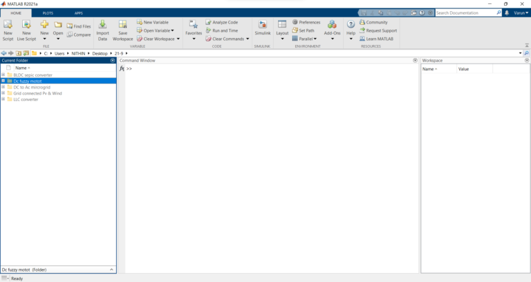
2. Open MATLAB and click on Simulink icon on home tab
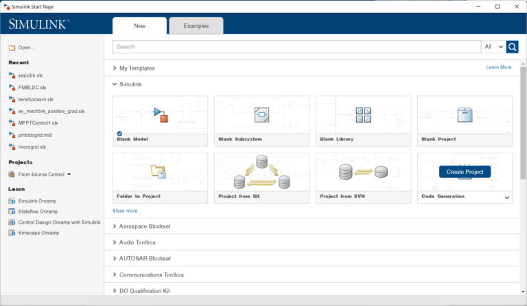
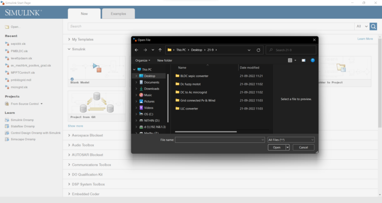
3. Click on open when the following window pops up
4. A window pops up from which select the required file and click on open
5. Once the file is opened, click on run which is in the simulate tab.
Result
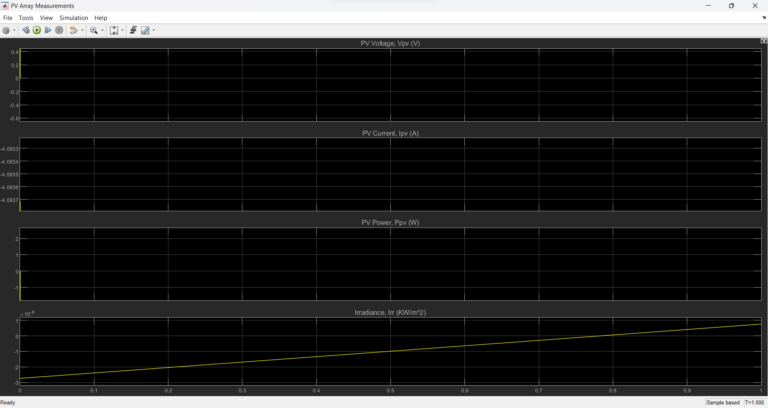
PV Array Measurements
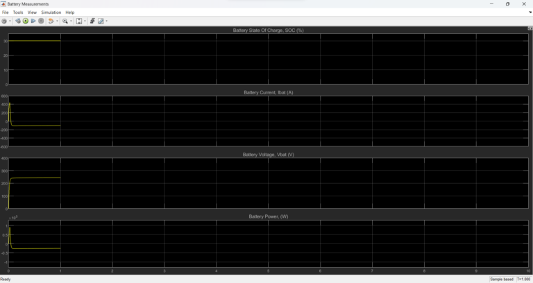
Battery Measurements
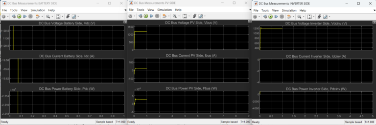
DC Bus Measurements
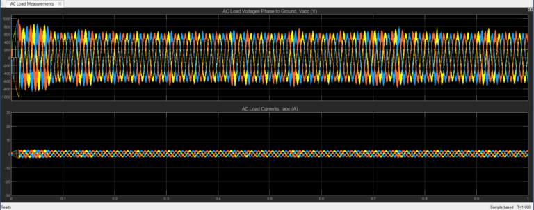
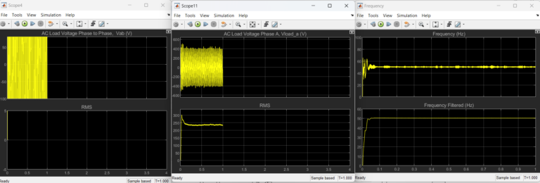
AC Load Measurements
Issues Faced
The default ratings of the PV array block, Fuel cell and battery should be chosen according to our requirement. Inverter and Converter operation requires pulse width modulation of converting Ac to Dc or Dc to Ac the timing of PWM and frequency of PWM replicates the conversion operation so, we need to give proper PWM to inverter and Converter.