Inverter is an electronic device used to convert direct current(DC) into alternative current(AC). Inverters can also be called AC drivers or variable frequency drivers(VFD). They are used in solar systems, adjustable-speed ac motor drivers, UPS(uninterrupted power supplies), power transmission industry etc. The Cascaded H-bridge multilevel inverter is one of the three main types of multilevel inverters.It was mainly developed for utility applications. The permanent magnet synchronous motor(PMSM) is an AC motor with a sinusoidal EMF waveform. It is widely used in actuators, robotics, machine tools, traction, aerospace technology, automobiles and is very much considered in industrial drives, vehicular propulsion etc. As there is no stator power for magnetic field production in PMSM, the power density is higher than one of induction motors with the same ratings. PMSM has low torque ripple effect and has higher operational efficiency with no magnetising current. In this paper a cascade multilevel inverter is fed to PMSM.
Code Description & Execution of Cascaded H-Bridge Multilevel Inverter
Algorithm Description
Modelling of PMSM : The diverse model of PMSM was derived using a two phase motor in d-q (direct and quadrature) axes. This model contains magnets and the rotor has no windings. These magnets concentrate all its flux linkage only on one axis as they are moulded as current source. The sum of resistive voltage drop is equal to the d and q axes stator voltage
Derivative of flux linkage with respect to windings :
Te=(3/2)(P/2)[λaf+(Ld-Lq)ir dr]ir qr (N.m) : used to calculate electromagnetic torque.
The above is used to calculate mechanical speed of rotor.
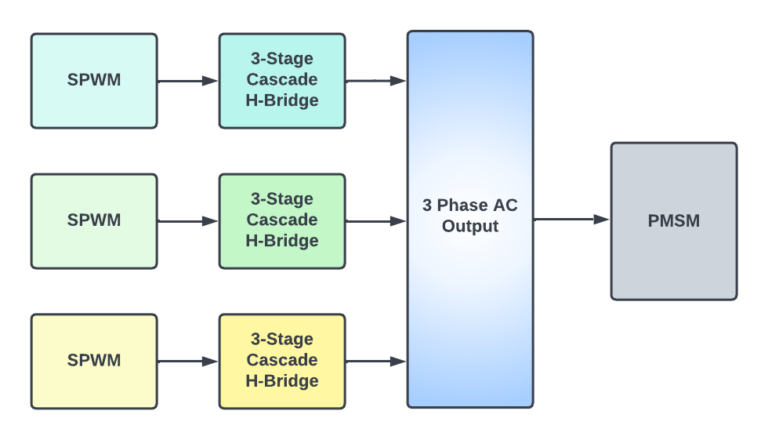
Block diagram of Cascaded H-Bridge Multilevel Inverter Fed Pmsm
MODEL DESCRIPTION
There is only one file to execute : level7pdasm.slx
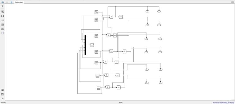
The above simulation is the circuit diagram of PWM(pulse width modulation).
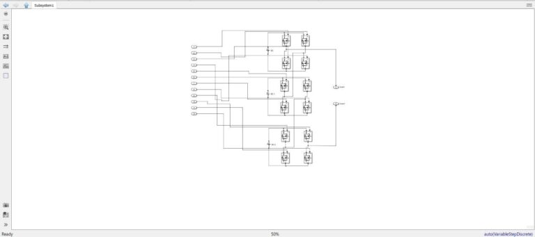
The above simulation is of three stage seven level cascaded H-Bridge inverter of first phase.
Note: simulink file or codes are saved in .slx format.
Steps to Execute the Code
Download the zip file and unzip it
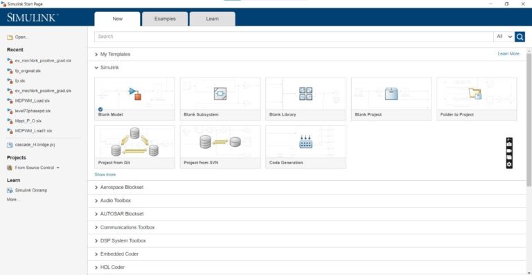
Open matlab and click on simulink icon on home tab
Click on open when the following window pops up
4. A window pops up from which select the required file and click on open
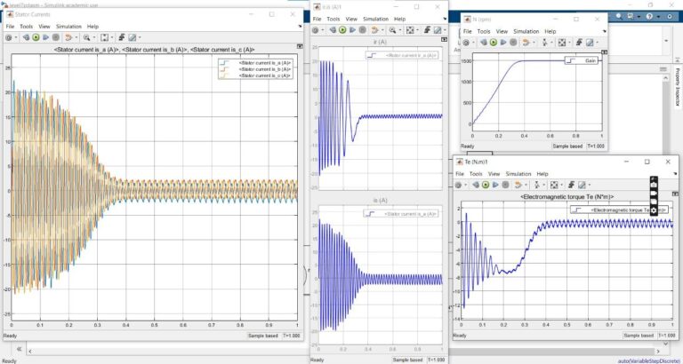
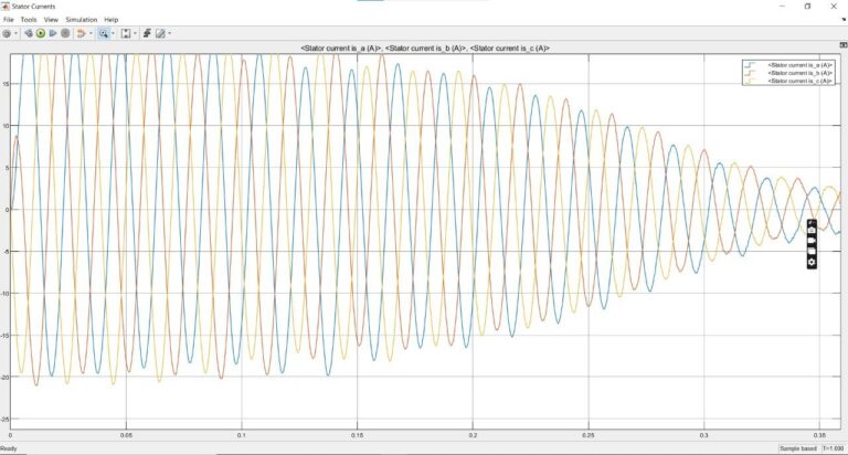
5. Once the file is opened, click on run which is in the simulate tab. Once the simulation is ready click on scope to view the results.
Result of Cascaded H-Bridge Multilevel Inverter
Issues Faced
Because of the version difference, functions might have changed and errors might occur so change functions according to the version(this simulation was done on R2022a).